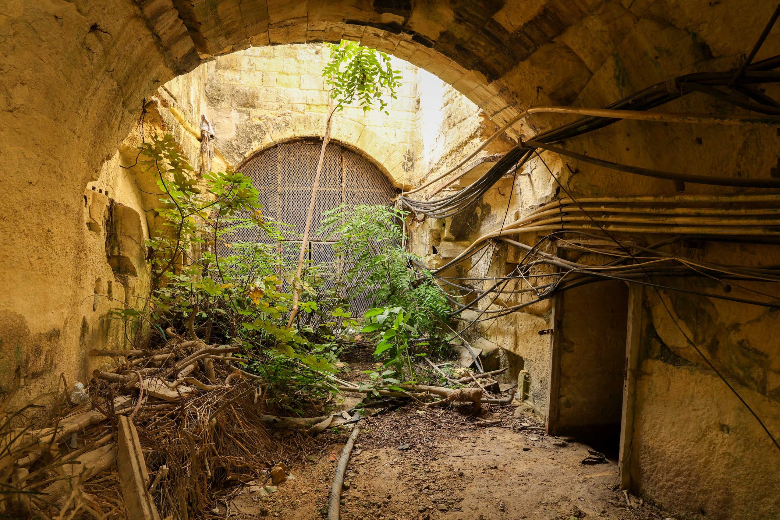
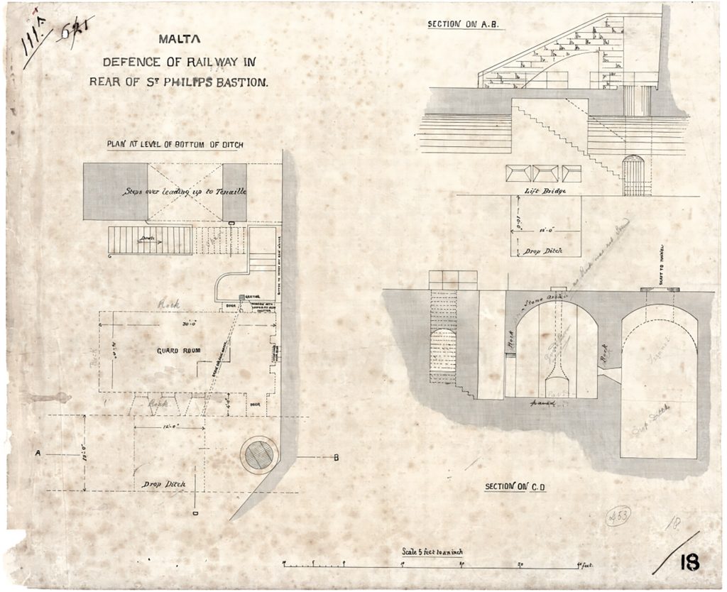
I’ve been ruminating for a long time on the evidence we saw in Floriana tunnel outside the guard house. This is the site indicated on the original 1882 construction drawings for a drop ditch and “lift bridge”.
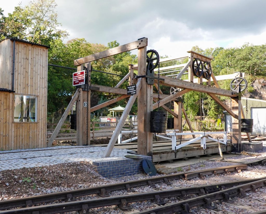
A lift bridge is a specific type of structure – a scarce and unusual type of moving bridge that rises vertically up, unlike a drawbridge or bascule bridge that rise from bearings at one end.
There are a number of surviving examples, most of which can be described as a rickety four-poster bed frame. The mechanisms are counterweighted at the corners and can be lifted with limited effort. A good early one of simple structure and mechanism has recently been restored at the Mountsorrel Railway The Stephenson Lifting Bridge. Another, the Leamington Lift Bridge in Edinburgh is a later example from 1906 Leamington Lift Bridge – Wikipedia.
What these and other examples show is that such a structure outside the guard house would have been difficult to accommodate due to the narrow width of the tunnel and the limited space available to install a frame. Whilst the original 1882 drawing allows for a raised section of vault into which such a bridge could ascend, there’s no accommodation made for the structure, mechanism, or drops for counterweights.
I’ve explored the evidence in the tunnel and the distinctive scars in either wall don’t seem to offer any logical solution to how a lift bridge could have worked. Equally, a lift bridge has strategic weaknesses as a defensive structure where any elements or mechanism left exposed to approaching attackers would be easily sabotaged. The need to have a regular frame and counterweights in each corner means that those located on the outward side would be vulnerable.
Lifting a bridge out of the way may have exposed the drop ditch in front of the gun emplacements, but it would also leave the length of tunnel exposed to enemy fire. The drop ditch could still be bridged relatively easy by any attacking force already in the tunnel. Instead, a drawbridge or bascule bridge is more sensible as a defensive measure, one that would simultaneously block any onward passage towards Valletta as well as offering a protective shield from which defenders could shoot from.

What this implies is that the proposed lift bridge in the tunnel was replaced by something else. That something existed here is evidenced by the scale of the recesses and structural elements still visible, and their symmetry on each side. The question is, what was the alternative solution employed here?
Returning to the evidence from the tunnel, the features are more concentrated at the Valletta side of the guardhouse. This asymmetry, which counts against a lift bridge, is more supportive of a more traditional draw-bridge pivoted at that end of the tunnel.
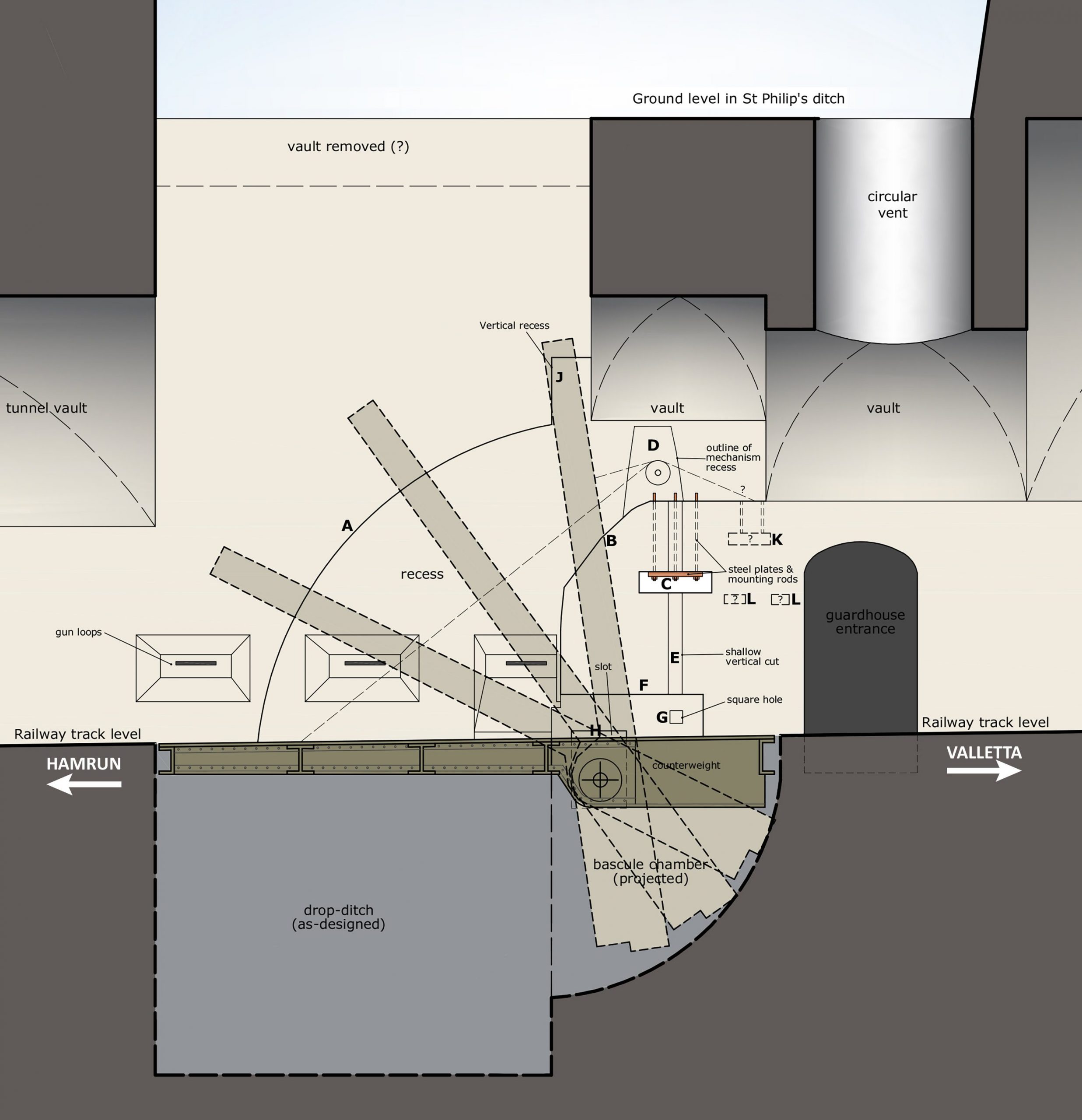
Looking in detail at the scars, filtering-out the many later service channels, the most obvious are the pair of deeply incised curved recesses (A). The outer radius of these prescribes a regular curve with an implied centre-point somewhere between the gun loops and guardhouse door and a radius of 10′ and a half or 3250mm .
The inner radius (B) is irregular, angular, and appears more mismatched between the two sides. The recess then continues back towards Valetta at high level as a short straight horizontal rebate immediately beneath the springing of a shallower portion of the tunnel vault.
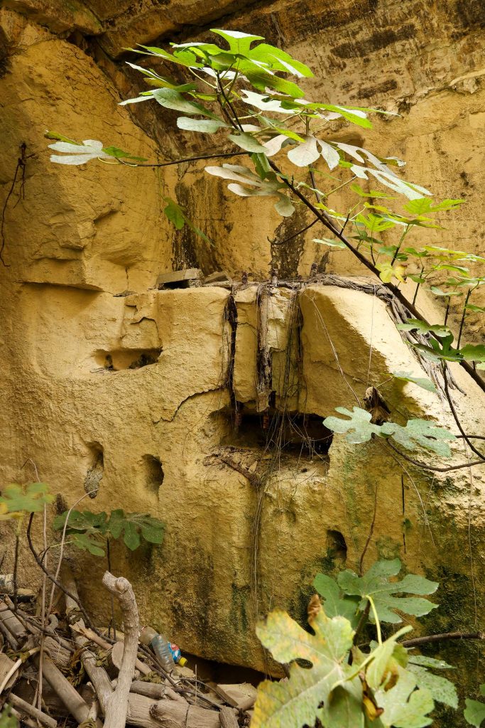
Within these deep horizontal rebates, on both sides, are located the stub ends of six substantial threaded iron rods. These rods are drilled directly down through the side of the tunnel and fastened firmly with metal plates and nuts visible in rectangular recesses below (C). Those on the south side of the tunnel have been exposed by spalled and damaged stonework.
What this shows is that something, now missing, was mounted here, secured very firmly down at the head of the curved recess. Careful inspection also shows shallower cuts into the side of the recess above each of these points (D). This is evidence of whatever structure was fastened here, and the minor adjustments needed to fit it comfortably against the walls.
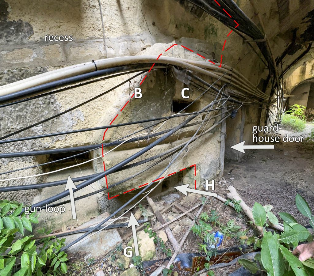
Less obvious features cut into the rock included a vertical indentation on the same line as the rods, one that over-sails the recess containing the steel mounting plate (E). Beneath these again, at track level, there is a further purposeful and deep horizontal rectangular recess (F). Other holes are cut into the back of the northern of these, though the southern is less visible. A square hole (G) is aligned again with the mounting point, another closer to the gun-loops is longer and lower in the wall (H) and continues below ground level.
Interpretation of these features is complicated and what’s presented here is a best-fit hypothesis. It suffers too from a lack of definitive survey information, that being used currently being a composite of a rough photogrammetry model, the original guardhouse drawing, and some judgement by-eye.
What is certain is:
- There was a substantial feature in the tunnel at this location
- It coincided with the location of the guard house gun-loops
- It was contemporary with the guard house as a tunnel fortification
- It included elements that were tightly bolted down into the sides of the tunnel
- The principal structures were mirrored on both sides of the tunnel
Missing from the picture is:
- No clear understanding of below-ground features
- No known comparable structures for comparison
- No documentation
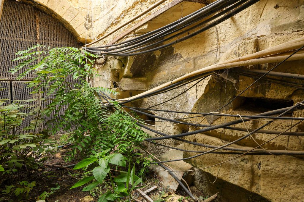
- confusion caused by post-railway alterations (particularly service runs), WWII use, vegetation and delamination and decay of the stonework
The most telling piece of evidence is the regular curve cut in the wall; this prescribes an arc within which something moved. Here, we are postulating that this accommodated part of a drawbridge with cables or chains used to raise the bridge deck from horizontal to upright positions.
The lost element once mounted on the steel fixings is likely to have been the mechanism that hauled the bridge deck into the vertical position. The inner curved cut was required to accommodate the angle of the cables when the bridge was in the lowered position.
Any bridge need to the full width of the railway tunnel if the drop ditch was to prove an effective defensive obstacle. It would have been limited in length by the tunnel vault, an issue somewhat addressed in the original drawing by raising the section above it to give greater headroom. Here, we have assumed the same dimensions as the originally proposed ditch for the bridge to have crossed.
Any bridge, whether moving or not, would need to withstand the weight of trains passing over it, so we can assume a reasonably heavily engineered structure was required. This raises the issue of weight, and how the bridge would have been raised.
The most likely explanation is that it was counterweighted, finely balanced so that it could be raised with minimum manpower and effort. It’s possible that the counterweights were separate from the bridge deck similar to the historic lift bridge examples. This would require a gravity drop into which the weights could descend for both sides of the bridge. There is no clear evidence for where or how these could have been integrated into the tunnel walls without fouling the passage of trains.
More plausible is that they were integrated into the bridge deck itself, the whole forming a bascule bridge rather than a traditional drawbridge. This would depart from the original drawing in that a larger pit would be required for the counterweighted end of the bridge to pivot into.
Two vertical cuts (J) may have housed locking mechanisms for the bridge at its top end when raised, or perhaps stays to prevent the bridge colliding with the vault. A horizontal slot at track level (H), now largely filled-in, is immediately above the centre point of the arc and would be where its bearings would have been housed.
More problematic is how the bridge was raised, that is to say, how was it operated. It would need to be lifted from both sides simultaneously to avoid excentric loading. A manual winding mechanism is likely, probably using a hand-crank. Whether there were separate winding mechanisms for each side, or if there was a geared mechanical connection across the tunnel isn’t clear.
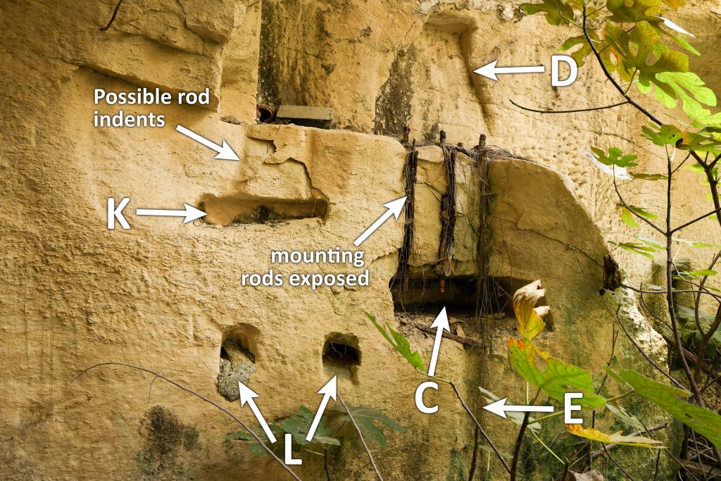
There is possibly more evidence of another element clamped down to the back of the main recess. At least one slot appears on the southern side of the tunnel with the face of the stone broken away above it and indentations that might be two channels for rods (K). More investigation needs to be made of this and the same location on the north side of the tunnel where it may exist concealed behind cables. Two socket holes immediately beneath the slot (L) may also be repeated on both sides.
These features may relate to a winding mechanism, or it may have utilised the shallow vertical channel (E) for which no other use can yet been attributed. It could have accommodated rotating shafts with bevelled gears meshing with other mechanisms at top and bottom, but no fixings appear to have been made into it.
There’s a lot of scope to discover more about this exceptional site; these sort of defences in railway tunnels are virtually unknown. Aside for better surveying of the site and cleaning up of the cables, the below-ground features must surely survive for archaeological excavation that could answer many outstanding questions.

No responses yet