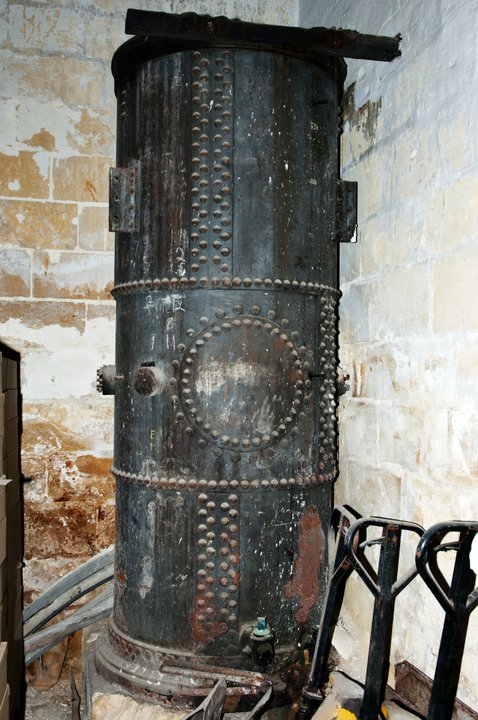
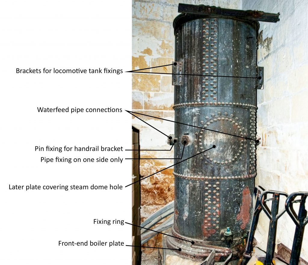
It’s been recorded, photographed several times, but is it more than it looks? It’s a tall rivetted cylinder at the back of the engineering works at Hamrun. Most analysis of it has identified it as a vertical boiler used as power or hot water for the works, or a storage tank; however, this new theory challenges that assumption and potentially vastly increases its importance as an historic relic of the Malta Railway.
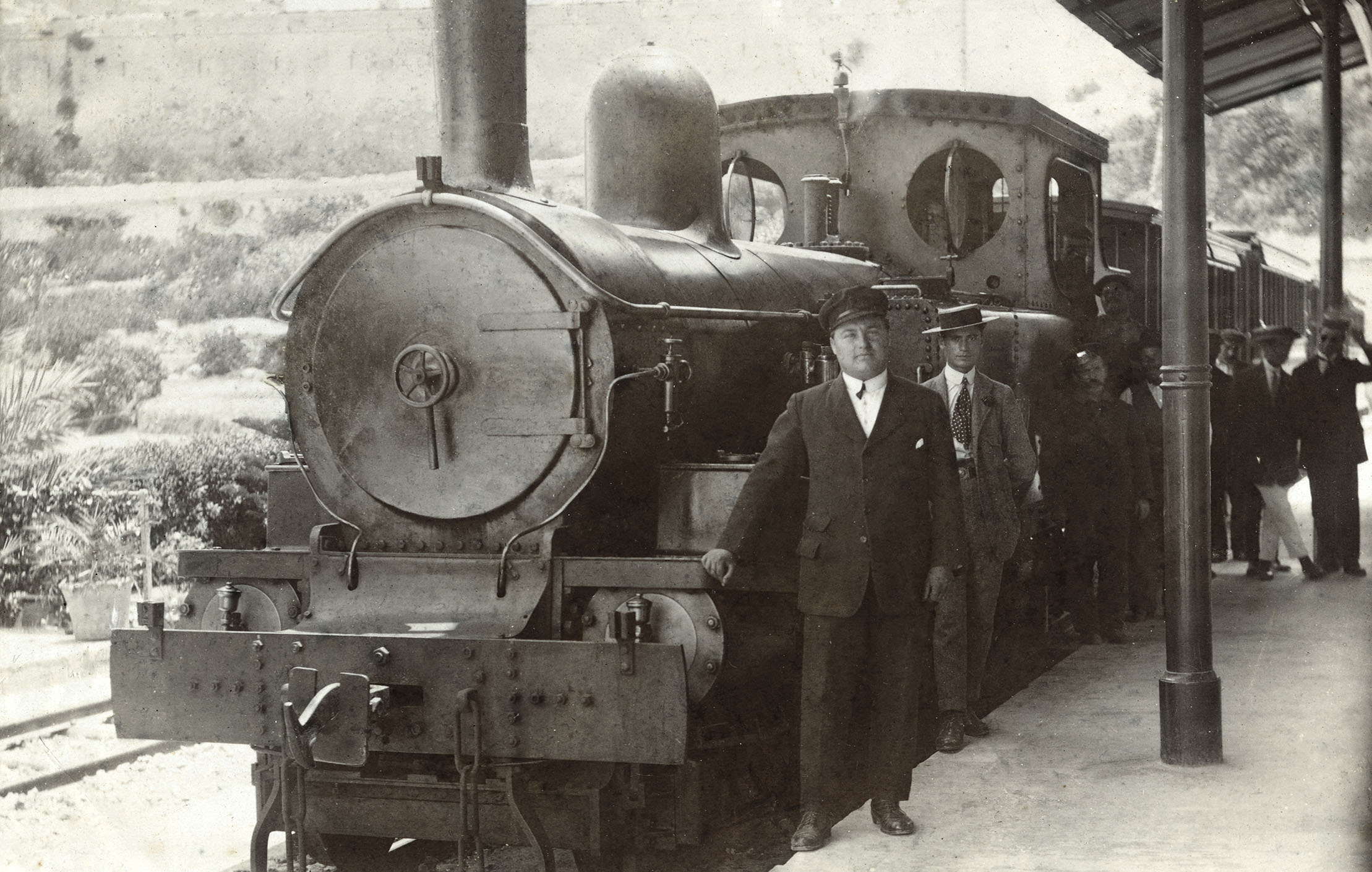
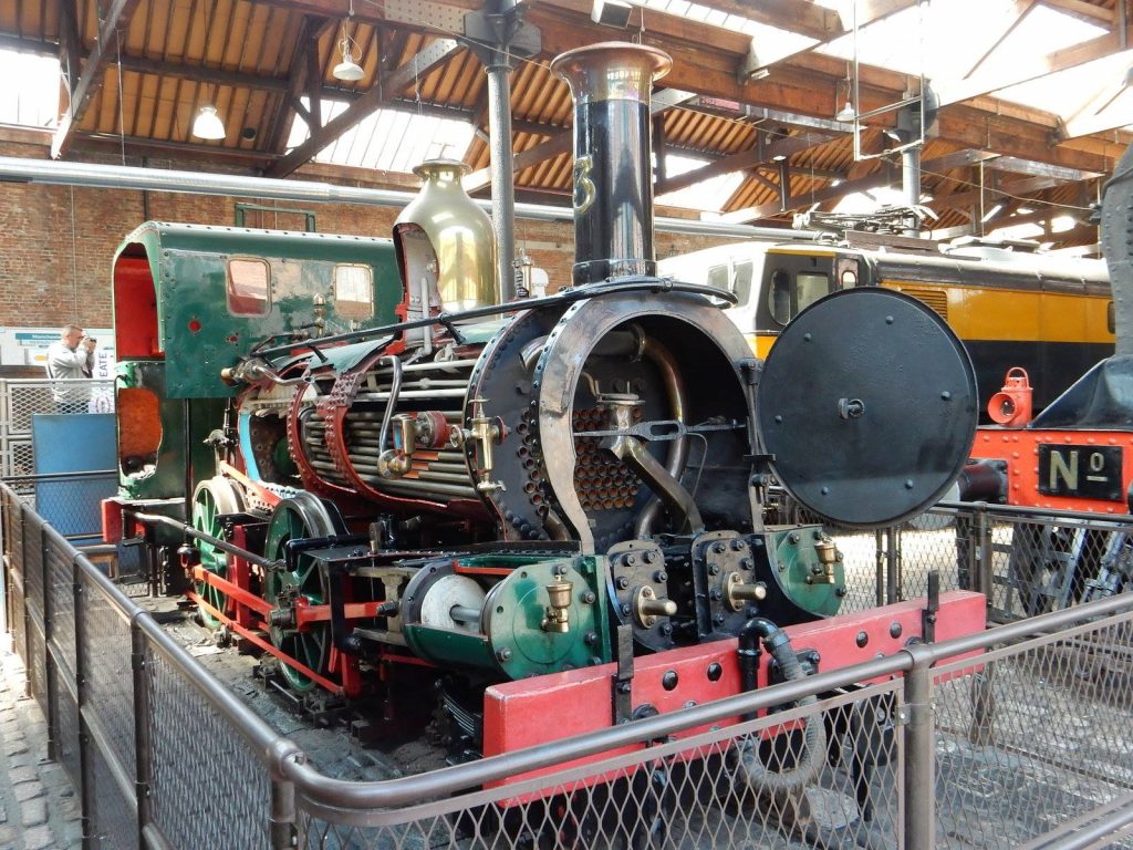
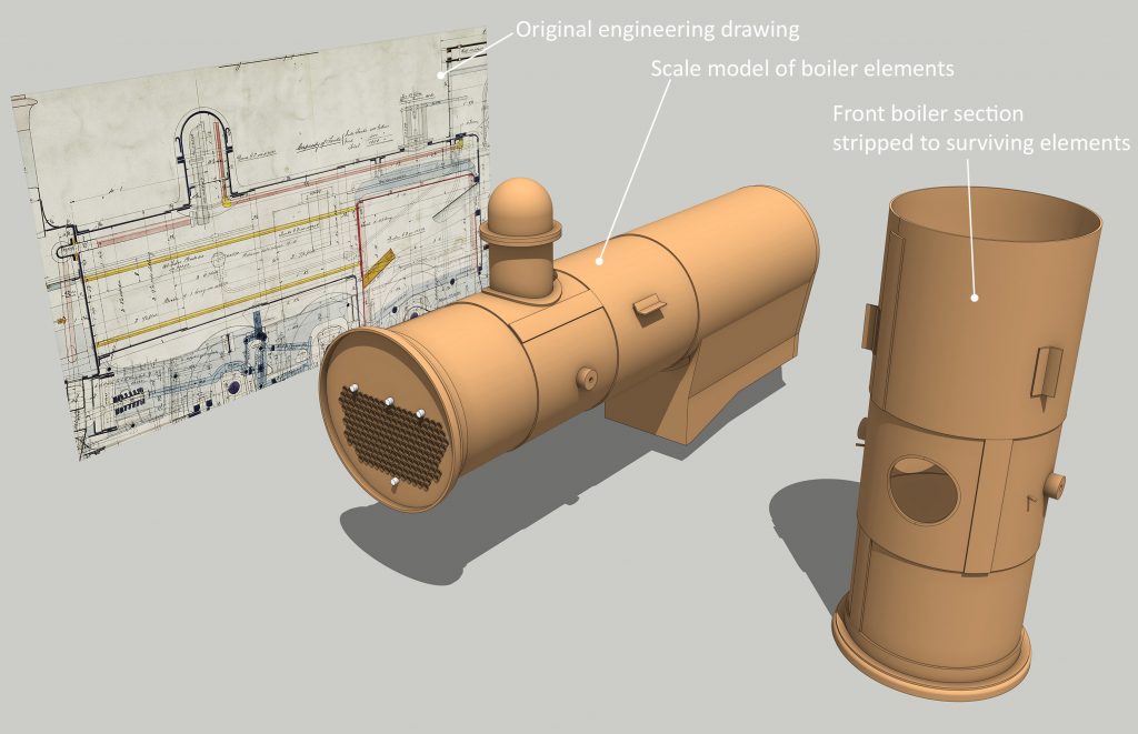
In a recent blog post we focused on why all engines on the railway faced in the same direction. Illustrating this we used one of the original manufacturer’s drawings of one of the four Beyer Peacock designed locomotives. Focussing again on this sectional drawing, a cutaway through the engine, it shows how all the components fitted together.
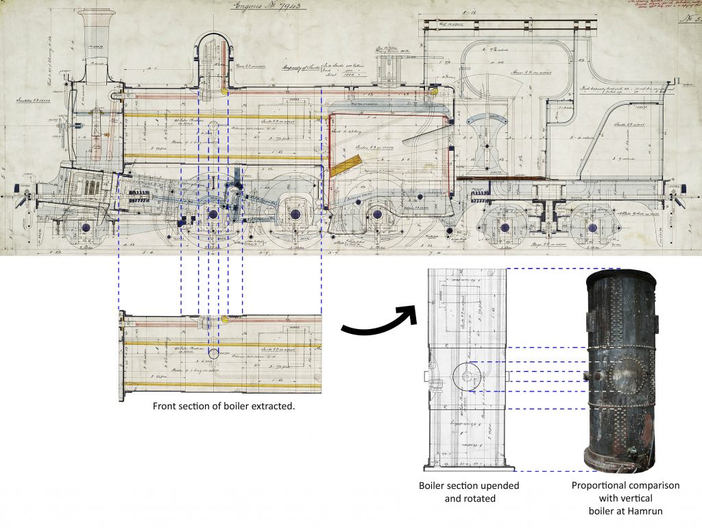
The drawing is colour-coded, red for copper, yellow for brass, brown for timber and shades of blue for ferrous metals, iron and steel. The horizontal form of the boiler is easily identified. This drawing shows how it was slightly conical in shape, being manufactured from several large barrel rings of graduating size that fitted over each other with a slight overlap, generally 2.5 inches.
However, none of these rings or the rivets that held them together are visible when you look at the outside of an engine; the whole is encased in a uniform cylindrical casing, partly for aesthetic purposes but also to form a cavity that could be packed solid with lagging to reduce heat loss and prevent the external surface temperature from causing injury.
Likewise, the elegantly shaped dome crowning the boiler was also aesthetic. The section drawing indicates the profile of the ironwork beneath, formed in sections connected by riveted or bolted flanges; this covers a hole through the boiler plates that accommodated the steam pipe.
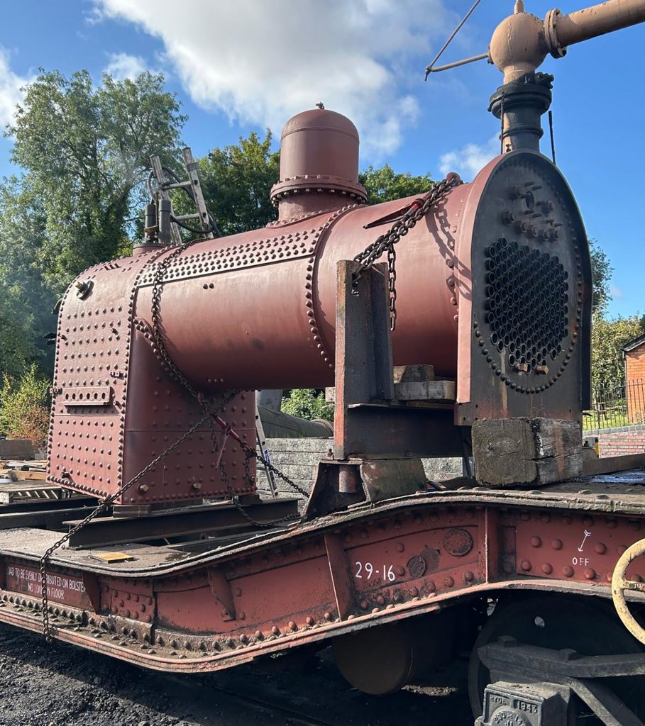
You’ll notice that the structure in Hamrun depot has some distinctive features in common. It too is formed from tapering rings riveted together, three of them. It also has a circular riveted plate with no other use other than to patch a circular hole beneath it.
You can probably already guess where this theory is heading, but further evidence needs to be considered before determining that this is one of the original locomotive boilers.
Notice the bottom of the vertical boiler in the depot and compare it to the profiles of the front-end boiler tube plate and the connecting ring fastening it to the first boiler ring in the drawing. They are very similar.
Proportionately, the first three rings of the locomotive boiler closely match the vertical example, a comparison made stronger by the locating of the steam dome centrally in the middle boiler ring; this would account for the circular patch.
Focussing on the front section of the locomotive’s boiler in the drawing and isolating it allows for more careful inspection. You’ll notice in the attached diagram that a circle is drawn in the centre of the extracted section. This was the connection for the feedwater pipe from the tanks into the boiler. This can be seen in historic photos just below the handrail fixing.
Taking things a stage further, rotating the section we’re interested in into an upright position, front-down, and swivelling it round 90 degrees so we can see the top, gives us an alternative view of the hole for the steam dome and the fixings on the side of the boiler. Comparing this to the surviving structure, the feedwater connections are obvious. One either side parallel with the patched steam dome hole.
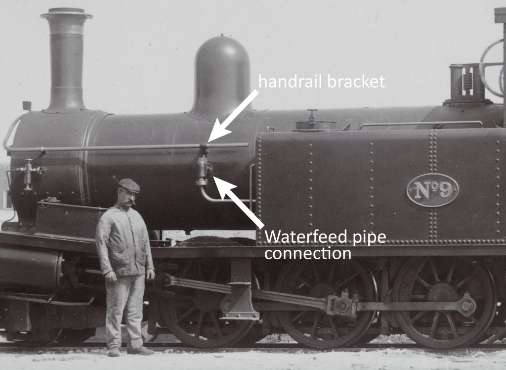
A careful look at the modern photo reveals other features. Also symmetrically positioned are two rectangular brackets attached to the uppermost ring; these are where the locomotive’s side tanks were secured. A metal pin projecting from the boiler side next to the feedwater connection corresponds with the bracket that once supported the handrail along the side of the boiler.
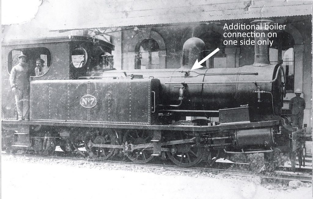
On one side of the boiler just near this pin is another cylindrical feature. I had assumed this was something added later, as most photos of the Beyer Peacock engines have nothing showing in a corresponding location. However, other photos show something, but only when the engines are seen from one side. This connection, therefore, is a unique signature that further supports the identification of the Hamrun boiler as being the principal section of one of these locomotives.
Boilers were regularly replaced on all the locomotives. They were constantly put under unique stresses caused by the nature of the line and its operation. The steep gradients required a constant high pressure to be available in one direction up the line. The many frequent stops at short intervals caused steam pressure to rise and fall rapidly in quick succession causing intensive repetitive fatigue of the metal components.
Engine No.7, bought in 1895, had a new boiler ordered from Britain ten years later in 1905. It was fitted the following year along with another replacement for No.8 on its own tenth anniversary. Fifteen years later both engines had them replaced again. No.9 was overhauled ten years after purchase, but it’s unclear if it too had its boiler renewed. Certainly it was replaced entirely in 1918 – another ten year interval. The last Beyer Peacock engine, No.10, began duties in 1905 but it’s twenty years in the records before note of a new boiler for it being ordered from the UK. A major overhaul might have been expected in 1915, but no specific record exists of what it would have involved.
This probably represents the frequency that complete boiler replacement was required: between ten and fifteen years. In total, six new boilers were ordered between 1905 and the closure of the line. Others may have been required, but the major overhaul of engines on a ten-yearly basis were otherwise managed by the engineering works. That they were capable of major boiler works is testified by the fact that none of the other engines are recorded as requiring new boilers purchased from their original manufacturers.
It’s little surprise that the redundant boilers, at least six in number, were recycled. Whether sent for scrap, melted down and cast into new items, or reused closer to their original purpose, they retained value. That set up on its end in Hamrun served a new purpose for the railway, possibly re-engineered to supply low-pressure steam for running machines in the workshop or simply as a storage tank.
It will take careful measurement of the surviving structure at Hamrun to provide unequivocable proof of its origins. Only then can it be compared with the accurate dimensions recorded on the original engineers drawings. But, all the evidence considered so far points heavily toward this as being the only major survival of a Malta Railway engine, a unique relic.

No responses yet