The Works
Construction & engineering
Planning a railway between Valletta and the old capital, Mdina, posed issues for any engineer. The old capital was 550 feet higher than the lowest point of the line, with challenging escarpments to avoid or, if necessary, ascend. The erratic terrain necessitated long embankments, cuttings, bridges, and large sections needing tunnelling through the island’s rock.
Use the links below to navigate through this page.
The project begins
The first six miles of line took exactly two years to construct, commencing in March 1881 with services commencing in March 1883. Progress was slow, a veritable soap-opera happening behind the scenes, stemming in no small part from the deteriorating relationship between the British railway engineer Frank Geneste and the embittered Mirabita family of contractors. Furthermore, the project was beset by bureaucratic delays and legal complications. On November 16th 1880 Geneste entered into contract with the Malta Railway Company to complete the line for £58,000 with a deadline set for the end of the following year. He sub-contracted the works to the Mirabitas on the 29th December. They’d previously been active promoters of the railway in Malta but were now reduced to being little more than manual labour under Geneste’s authority. By any stretch of the imagination, and without the ensuing complications, it would have been an extraordinary accomplishment had the challenging engineering works been completed in little more than twelve months.
Geneste had an extensive portfolio of railway building experience in England, India, Hungary, Venezuela, Columbia, and South Africa. Whilst he was clearly a skilled engineer and surveyor, his abilities in contract and project management, and management in general, seem to have been less definite. His lack of experience in Malta, and with Maltese law particularly, found him quite out of his depth.
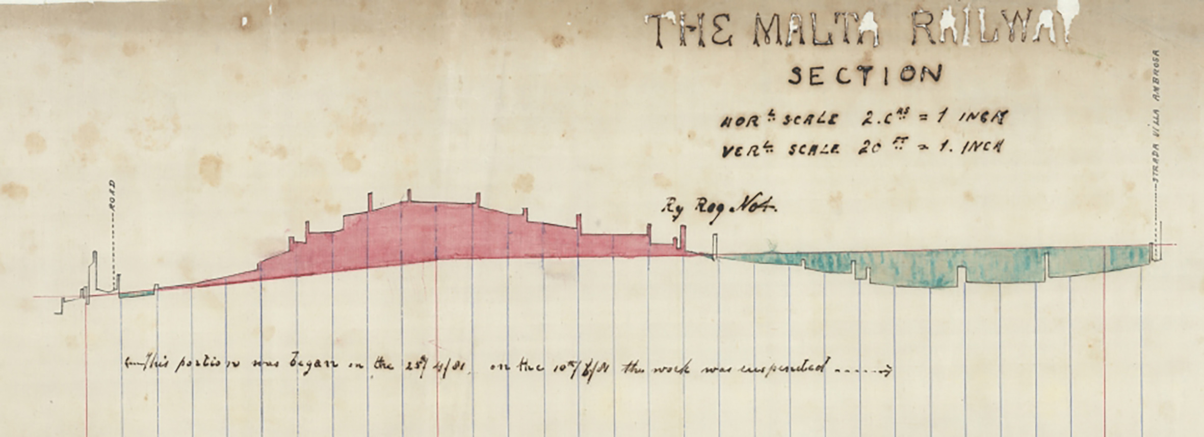
The Mirabitas had signed a series of contract drawings as part of their legal agreement which were to be supplemented by working drawings supplied by the company’s engineers, Wells-Owen & Elwes of Westminster. New drawings began to arrive in Malta early in 1881, issued to Geneste as principal contractor. All proposals had to be signed-off by a Government Supervision Board and by the War Office, both of whom had their own ideas about how best to conduct the railway works. Section drawings were the initial priority, showing how the line would address the island’s topography with gradients, cuttings and embankments, and illustrating where stations and crossings over and under the line were to be made. The alignment of the three-quarters of a mile long tunnel required between Valletta and the outer line of defensive works surrounding Floriana was also a priority; the tunnelling would be the most challenging work and need the most time to complete. Construction work is reported to have begun in March 1881, already four months into what was a short contract period.
The Government of Malta had consented to the compulsory purchase of land for the railway, but Maltese law did not permit access for surveyors or for any work to commence before purchase was legally complete. The railway met with resentment from farmers who had no interest in their land being taken from them or divided and sought to obstruct the railway. It wasn’t until April 23rd that the first parcel of land was purchased, and further progress was tortuous, even after further Government intervention eased the legal restrictions. Geneste later recounted that works had progressed “with great difficulty – field-by-field in fact”.
Dark clouds on the horizon
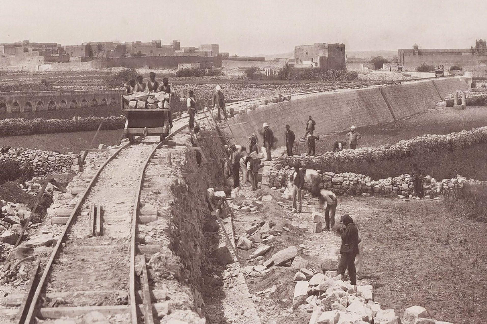
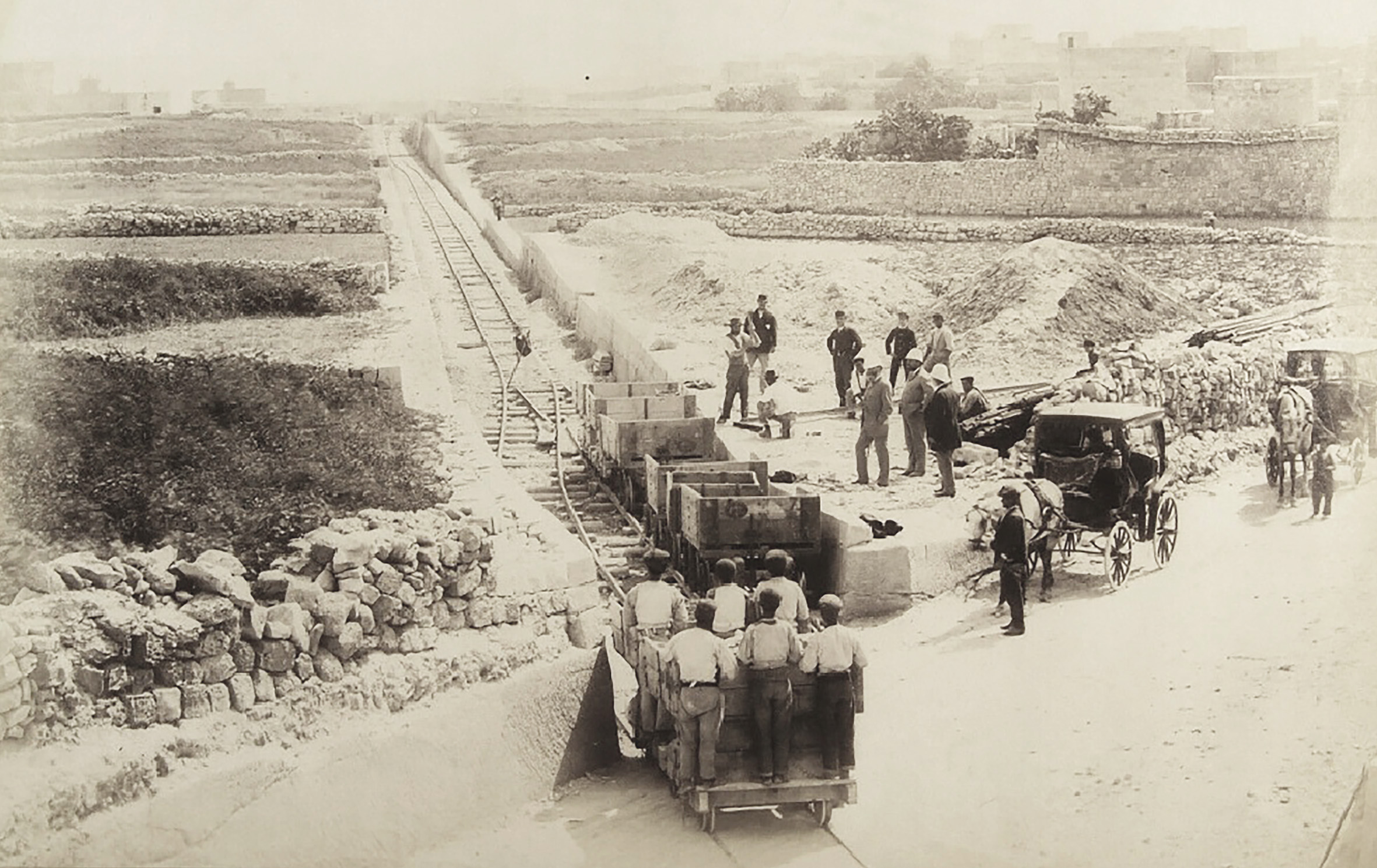
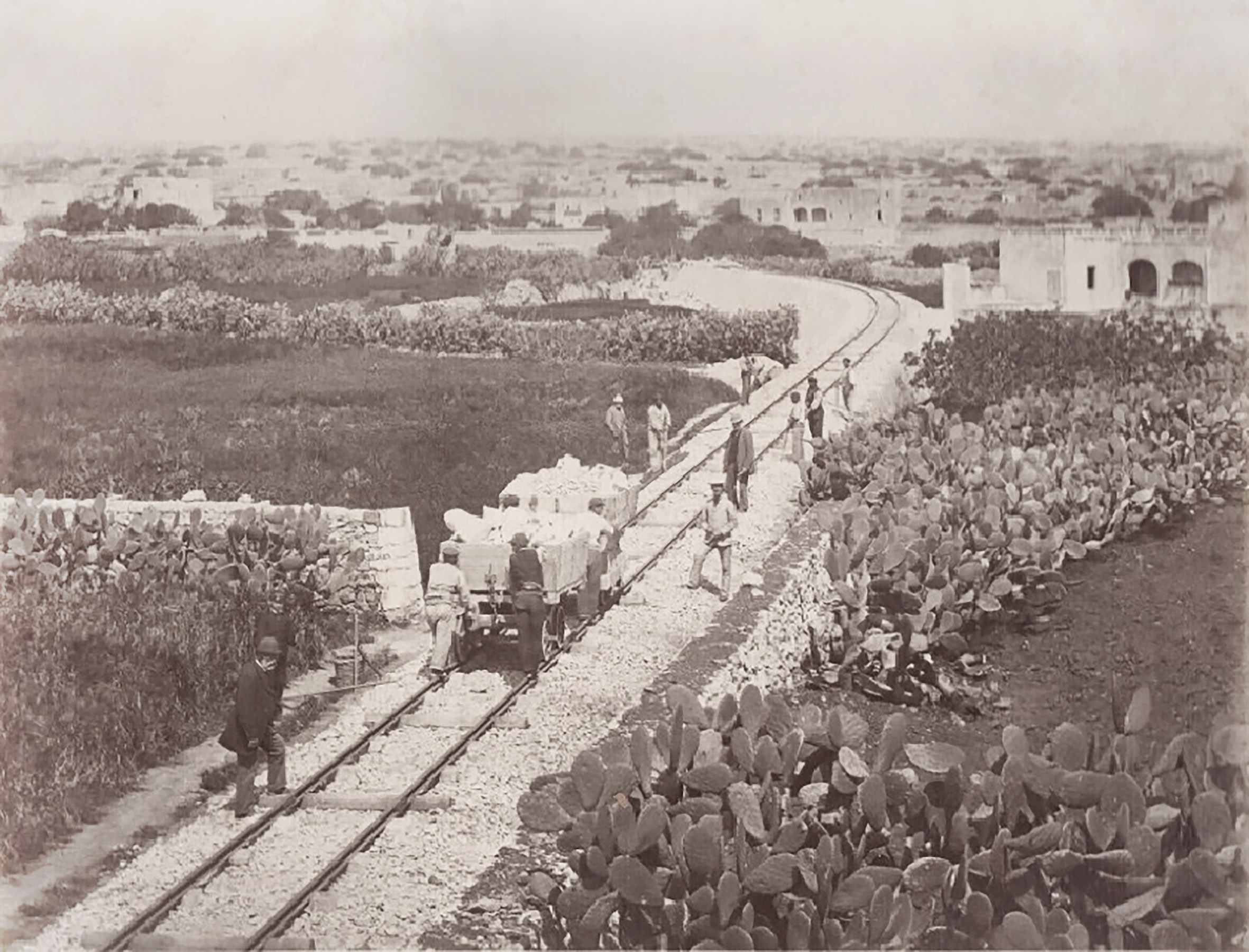
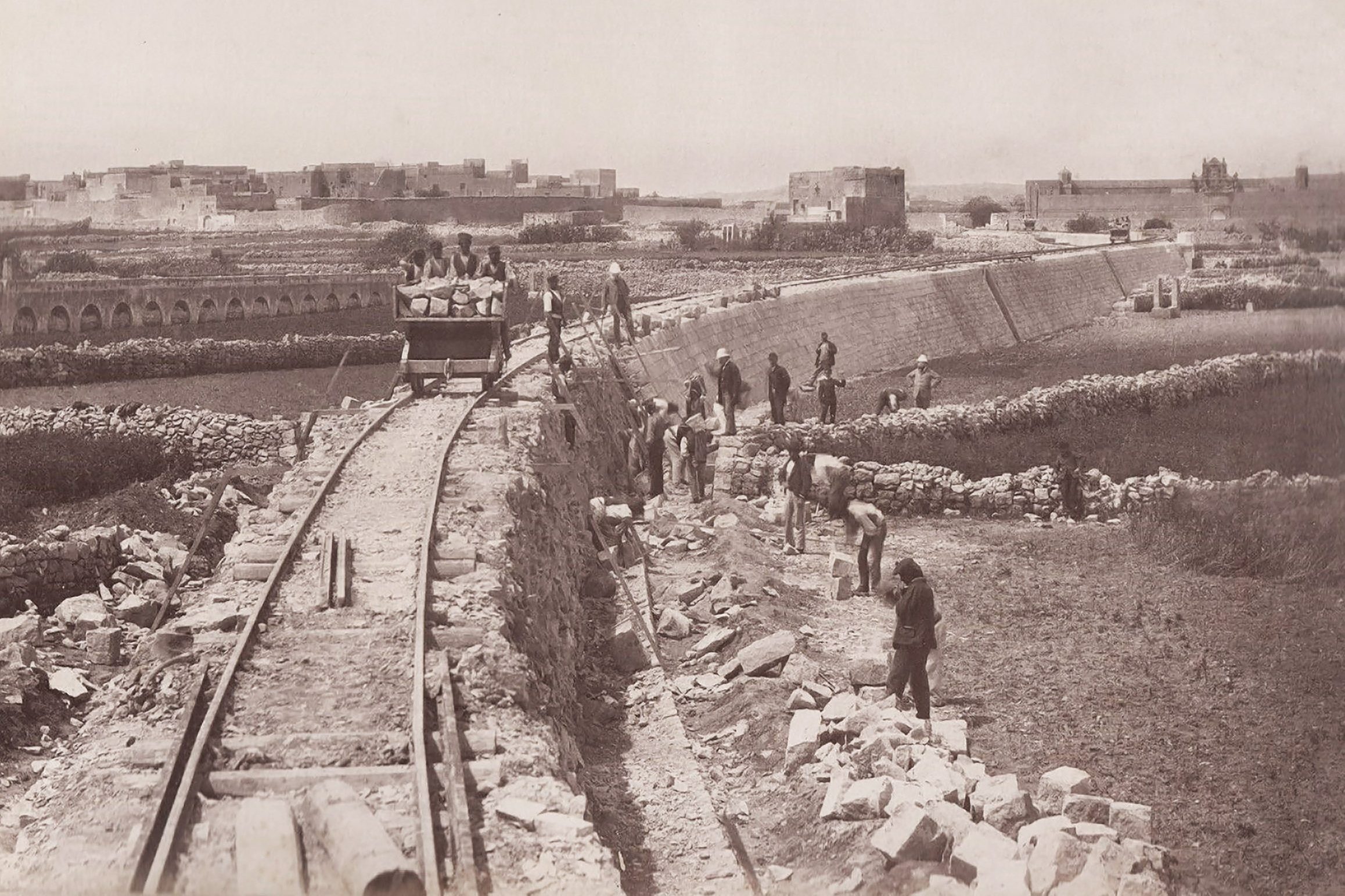
One of the railway’s engineers, Richard Elwes, read a progress report to the London shareholders in November that would have been demoralising news to investors. Work on Floriana tunnel had begun, with many of the shafts being started, but none greater than 18 feet deep and most considerably less. The track was reported as laid between the site for Msida station and Tal Fniec, somewhat short of Birkirkara, a length of 59 chains (around two thirds of a mile). The landscape along this stretch above the Msida valley was less than challenging, with the most basic engineering works required of almost any stretch of the line. Work had started in a third location, at Attard, where the contractors were actively digging the cutting in the direction of Mdina. Work here was described as “progressing fairly” and waggons were being used to transport excavated stone a short distance downhill to construct the Attard embankment. And that seems to have been it: the sum total of twelve months work; not even a mile of permanent way completed.
Much blame was directed towards the War Office, Supervision Board, and Maltese legal procedure for delays, but the deteriorating relationship between Geneste and the Mirabitas damaged construction progress. Investors must have been exasperated by reports of “endless disputes between them”, issues that came to a head when Geneste exercised a clause in the sub-contract and took part of the works out of their hands. Predictably, the subcontractors took legal action against Geneste, obtaining injunctions preventing any progress on that part of the work. Maltese law also resulted in the Malta Railway Company becoming embroiled, despite having no direct relationship with the sub-contractor. In this climate of escalating tensions the projected completion date of 31st December proved fantastical, and the deadline was missed.
George Wells-Owen, the other half of the company’s engineering partnership and a shareholder in the railway, arrived in Malta to inspect the beleaguered works early in 1882. He described finding “the relations of the Company were in a very unsatisfactory state and he succeeded in putting them on a proper footing”. Despite something of a hiatus in construction a series of drawings were issued for bridges and viaducts along the line, suggesting these were shortly to be commenced.
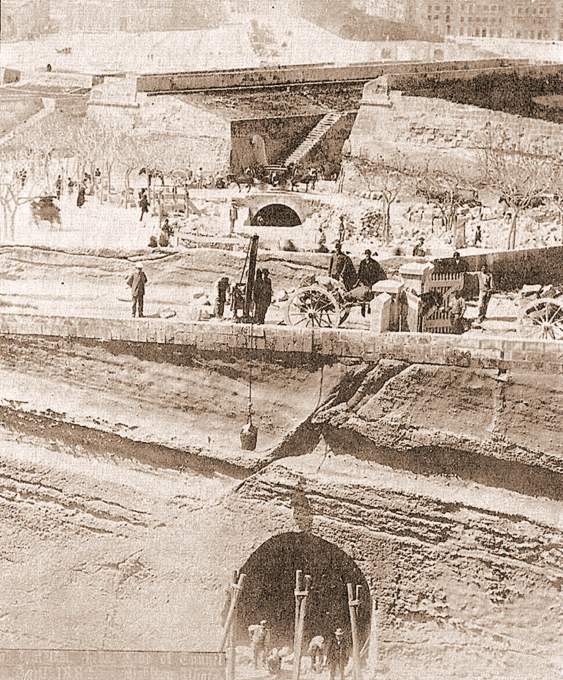
After some weeks assessing the situation in Malta, on his return to England in March, Wells-Owen was able to make a positive report on progress to the directors. He stated that the Floriana Tunnel was half complete, with all the shafts down to the level of the tunnel itself, land purchases were predominantly complete on the first 4 miles 47 chains, and embankments, cuttings and bridges on the first section finished with the track laid. There was a 500-strong workforce in employment, but more would be required if the line was to be complete by the end of the year. Delays, he suggested, were the result of the Government’s supervision board refusing to sign-off any further work until final plans for Valletta’s station were agreed. Once the report reached Malta it was savaged in a series of anonymous letters in the local press, presumed, by their detailed knowledge of the railway, to be authored by the Mirabitas. They accused the report of misleading shareholders about the state of the works, later claiming that the photographs take in April to reassure investors showed the only parts of the line then complete. These accusations appear to have had some basis in reality as some of the reported works detailed by Wells-Owen, for example the bridges, were later shown not to have been complete. The specially commissioned photographs were also focussed on a suspiciously limited set of locations.
William Roebuck’s rescue
It seems that Wells-Owen lacked the authority to resolve any of the legal issues and his report was sufficiently concerning for the Company to immediately dispatch William Roebuck, one of the directors (also a civil engineer) to Malta. In April 1882, less than a month after Wells-Owen’s return, Roebuck found himself landed on the island with instructions to sort the mess out. His diplomatic intervention with the Island’s officials and Governor agreed a nine month extension for completion, relaxing the threat of forfeiture of the works to Government. To remove the blockage on progress Geneste was relieved of his contract in August at his own request, “it being impossible for him to go on with it”. The Company were now in direct control of the works but engaged Geneste as “resident engineer”. For Geneste, his public failure and effective demotion must have been humbling, and it’s surprising that the Directors maintained confidence enough to retain him in a new role. The Mirabitas, given assurances and a financial offer by Roebuck, and no doubt satisfied at Geneste’s side-lining, reengaged with work to complete the railway though continued legal action in an effort to improve on the Company’s offer.
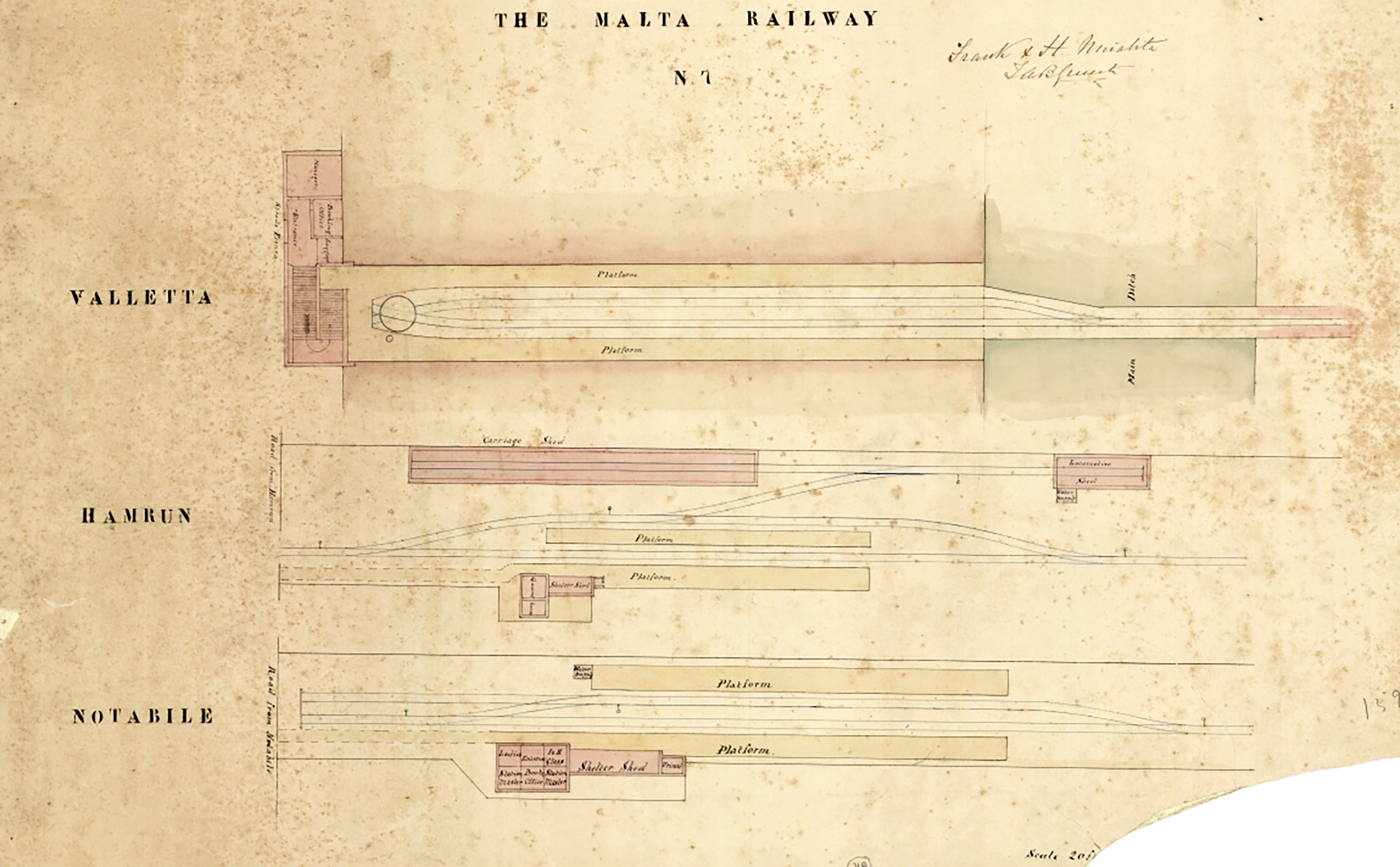
A list drawn up on the 1st June itemised the incomplete works; there were many significant obstacles yet to overcome. Despite Wells-Owen’s earlier claim, timber bridges across all of the ancient fortifications were still missing as well as that at Princess Melita Avenue where the road was also yet to be lowered. The bridge at Attard had not yet received its girders. Station buildings at Valletta, Floriana, Hamrun, Msida, San Anton, and Attard hadn’t been started, nor had the engine and carriage sheds at Hamrun. Defensive drop ditches and the underground guard room at St Philip’s Bastion had perhaps been delayed by the War Office’s slow approval of proposals and were still pending. A lengthy list of smaller works along the length of the line peters-out short of San Salvatore station, at around the point where the final mile of works to Notabile had yet to be started.
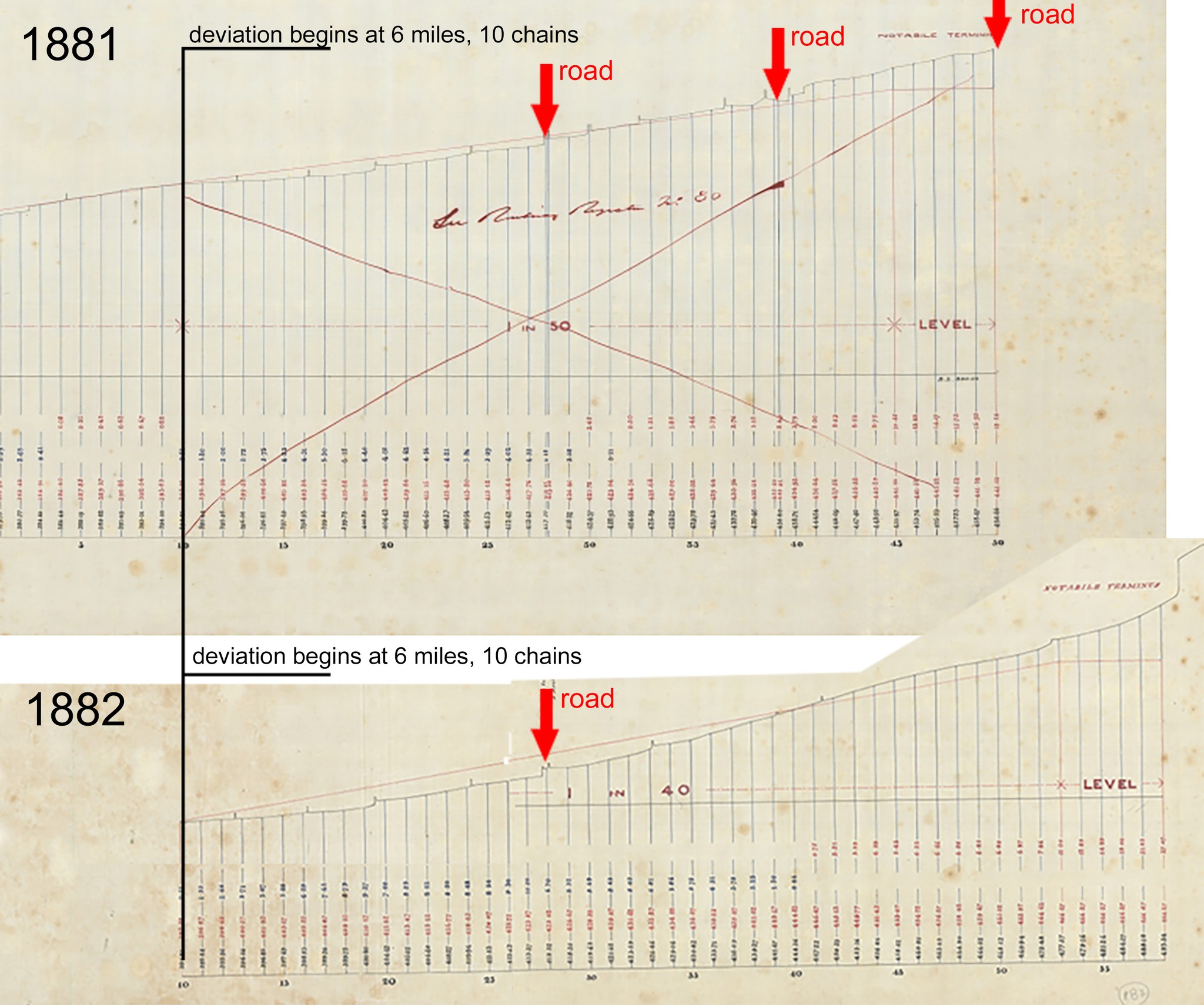
During his stay, Roebuck appears to have conceded to the Supervision Board’s complaint that the location for the proposed Notabile terminus was too remote from town. In April preparation work for the final mile had only just begun, but by the end of the month new drawings were issued to bring the line up to a new point closer to Saqqijja Hill. The deviation was slightly amended again in October with plans issued for the layout and station building shortly after; these were to be the last plans issued for major works on the line.
The final strait
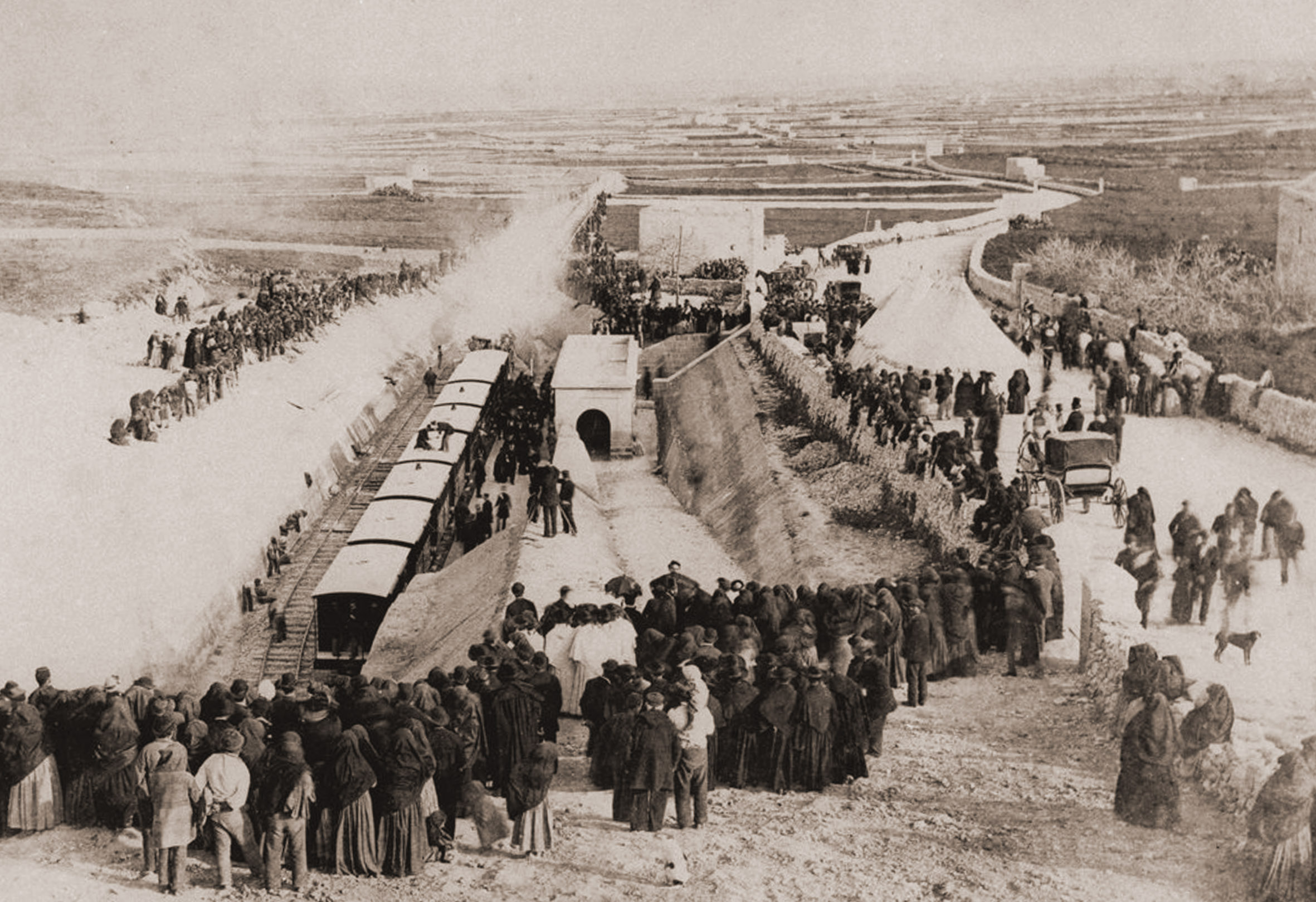
With some audacity, the Mirabitas congratulated themselves in the pages of The Malta Standard in late December 1882, laying claim for the successful completion of “a beneficial project which they had first initiated in 1874”. They repeated accusations that the present Company had treated them unfairly, claiming they had “been magnanimous enough to hand over their plans and drawings to the rival company” after the collapse of their first enterprise. The railway would, in fact, not open until Feb 28th 1883, the contractors no doubt trying to get the steal on the railway company for credit, and taking advantage by disparaging their reputation before the first train had even run. From close inspection of photos taken at Notabile station on inauguration, there remained many unfinished works that needed resolving in the weeks following.
The final cost of the line was put at £76,971 / 14s / 9d. with more than £5000 alone on land acquisition, far exceeding the original £1500 estimate. Financial difficulties had reduced the specification and quality of much of the infrastructure which would quickly lead to maintenance problems and passenger complaints. Lack of capital would prevent the line’s anticipated extension, or even the ability to run an adequate service, but the appointment of Geneste as General Manager and Engineer, despite the Company’s bad experience of his managerial abilities, would prove their ultimate undoing.
The world’s second underground railway network?
The railway was very unusual for the length of tunnelling that was required for such a small concern. The island’s topography was an immediate challenge for any endeavour. Linking the two most populous centres required challenging gradients to be tackled, ones that couldn’t be addressed through cuttings and embankments alone. The project could hardly have been considered a realistic proposition had it been faced with a more resilient geology to the easily cut Maltese rock
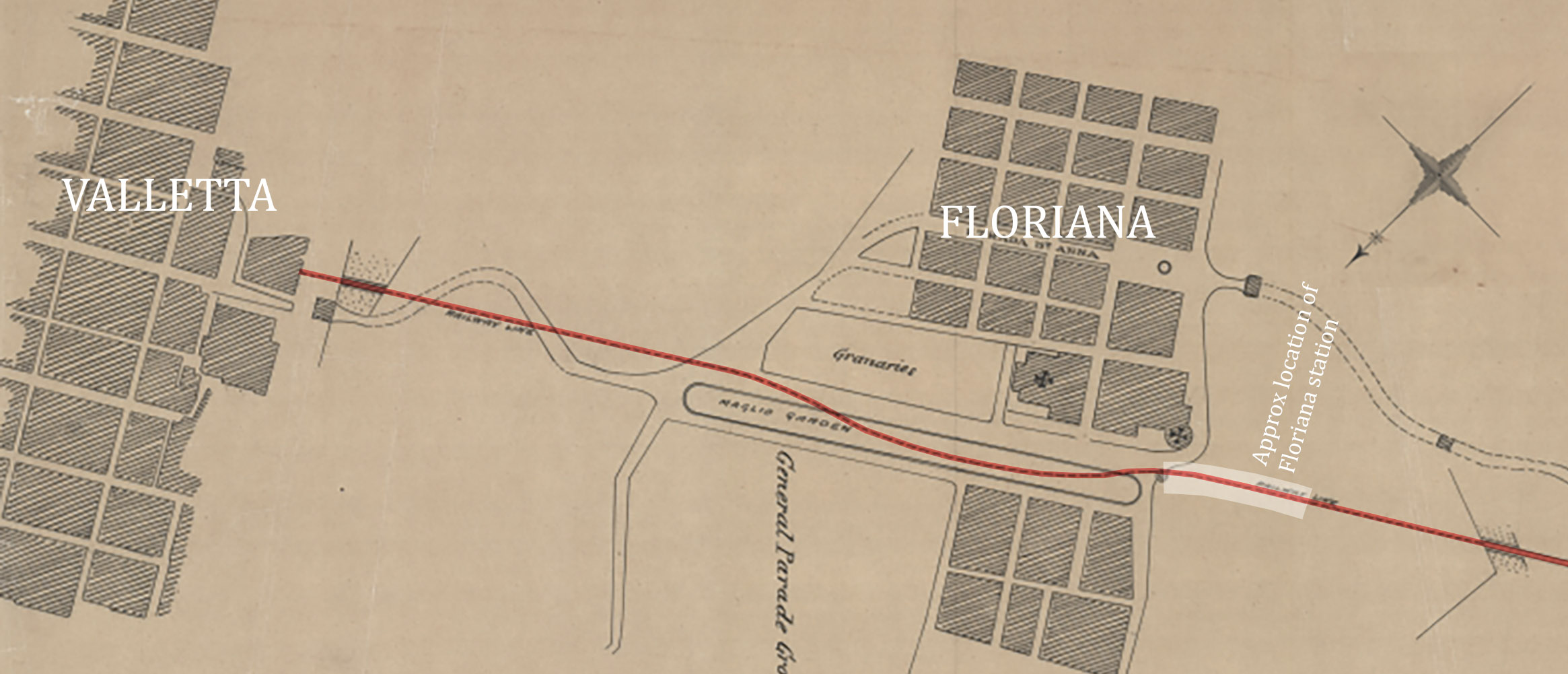
The route required three separate tunnels to be dug, the first being for Valletta station, the longest section beneath Floriana, and a short penetration through Floriana’s outer wall near Porte des Bombes. To this challenge a second tunnelling venture was added at the other end of the line, beneath Mdina, when the line was extended from 1896.
Though the original engineers, Wells Owen and Elwes, had worked on an extension to the Metropolitan railway, this 6-mile section was over ground, the partnership having little direct experience in the field of underground railways. Underground stations were another matter entirely, and wholly unusual outside London at the time. Although a short underground railway in Istanbul claims the title of the World’s second underground railway, both its stations were at street level and not actually underground. Malta, however, had Valletta and Floriana both at significant depth. Malta had a sterling case to claim the title of the world’s second underground network!
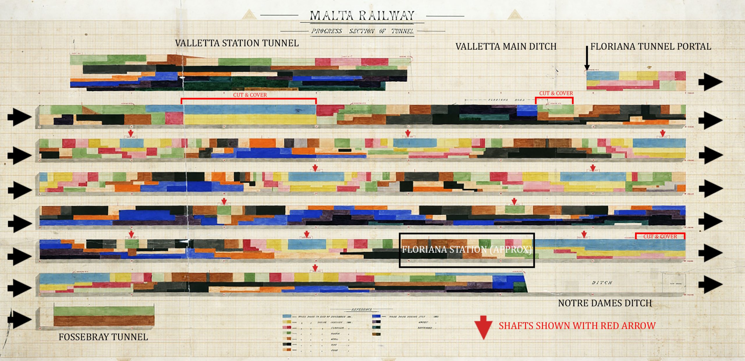
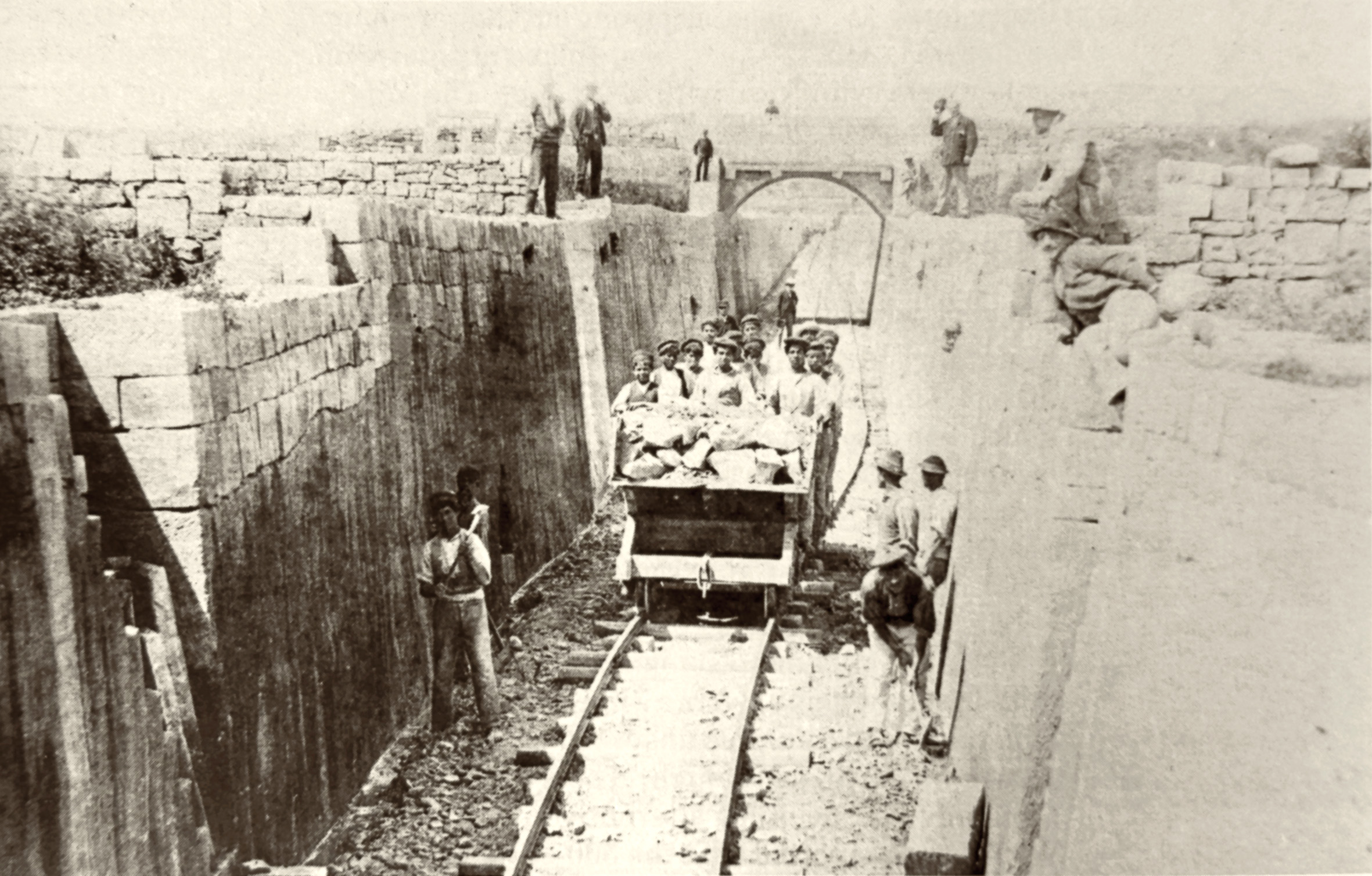
After a long series of delays tunnelling was amongst the first construction works on the railway, beginning at the end of December 1881. Rather than starting at the ends and working inwards, the plan was to sink eleven shafts and dig sections of the tunnel simultaneously. As well as this, there were two locations where the tunnel would be so close to the surface that a cut-and-cover approach was more economic. These were just beyond the main ditch where the road from Floriana crossed, and the gap between St James’s curtain and St Philip’s Bastion close to the location later used for Floriana station. The shafts would provide constant smoke ventilation to the tunnel, but the trench-dug sections of the line received a stone-built vault before being covered over.
The design of the tunnel needed to include a steep 1:60 gradient down from the capital, but an unplanned deviation had to be integrated to bypass an underground reservoir under St Publius church. Instead of the direct and consistent line hoped for a bend had to be introduced to curve around it before rejoining the intended alignment. The loss of direct line of sight down the tunnel, especially so close to Floriana station, must have been a perennial frustration for drivers.
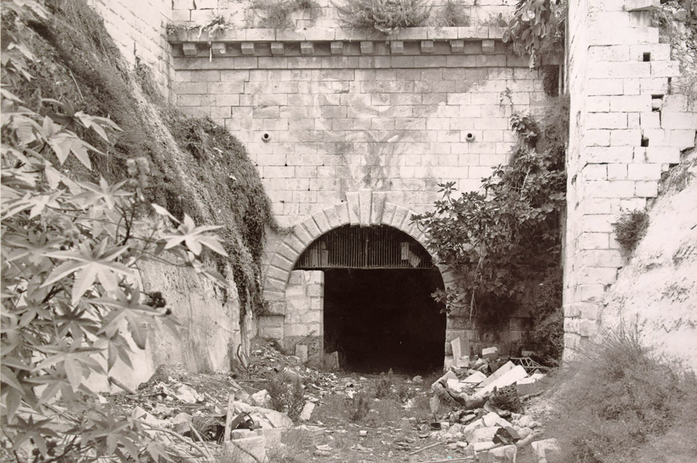
Two further shafts were sunk within Valletta to excavate the larger station tunnel from the inside out. The first opening into the Valletta ditch was in March 1882, but this was a small penetration, the final opening-out of the full width arch into the station being the very last work on the tunnels and not broken through until the end of the same year; this was perhaps to maintain the integrity of the city’s walls until all railway defensive measures were in place to the satisfaction of the military authorities. Most intriguing of these defences was an underground guard room.
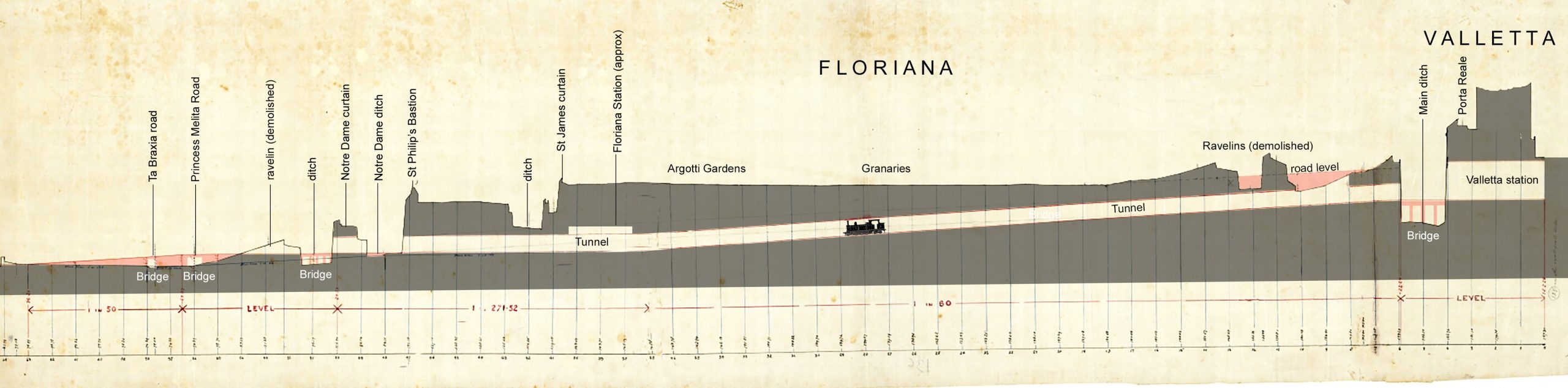
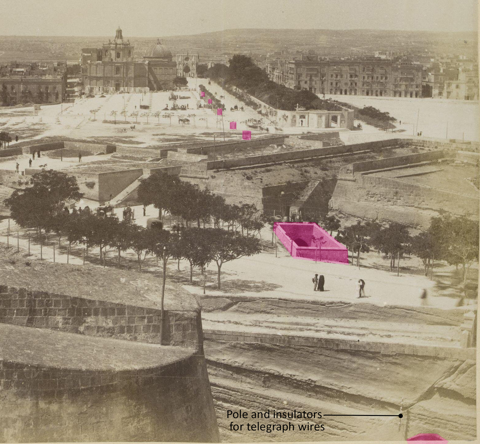
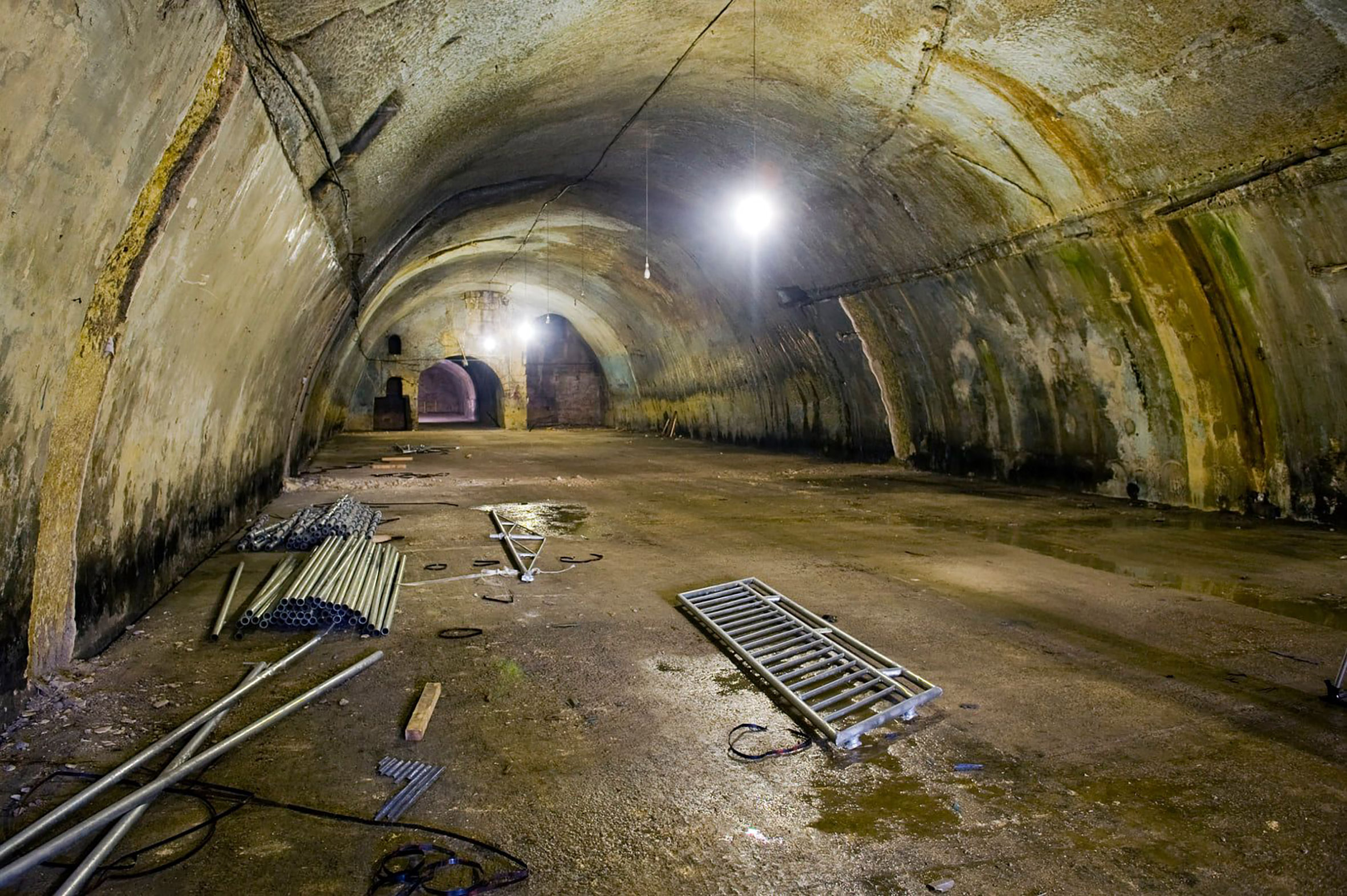
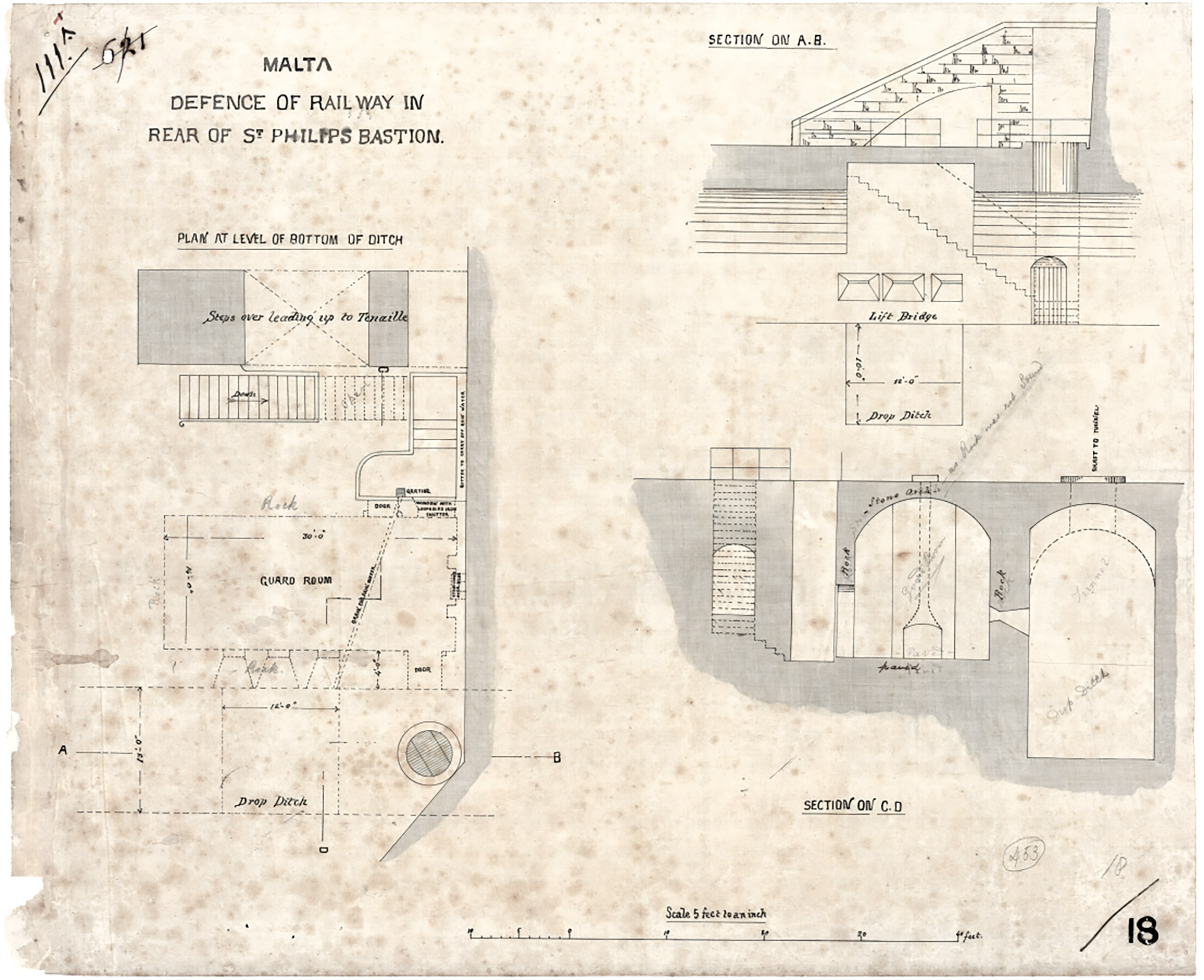
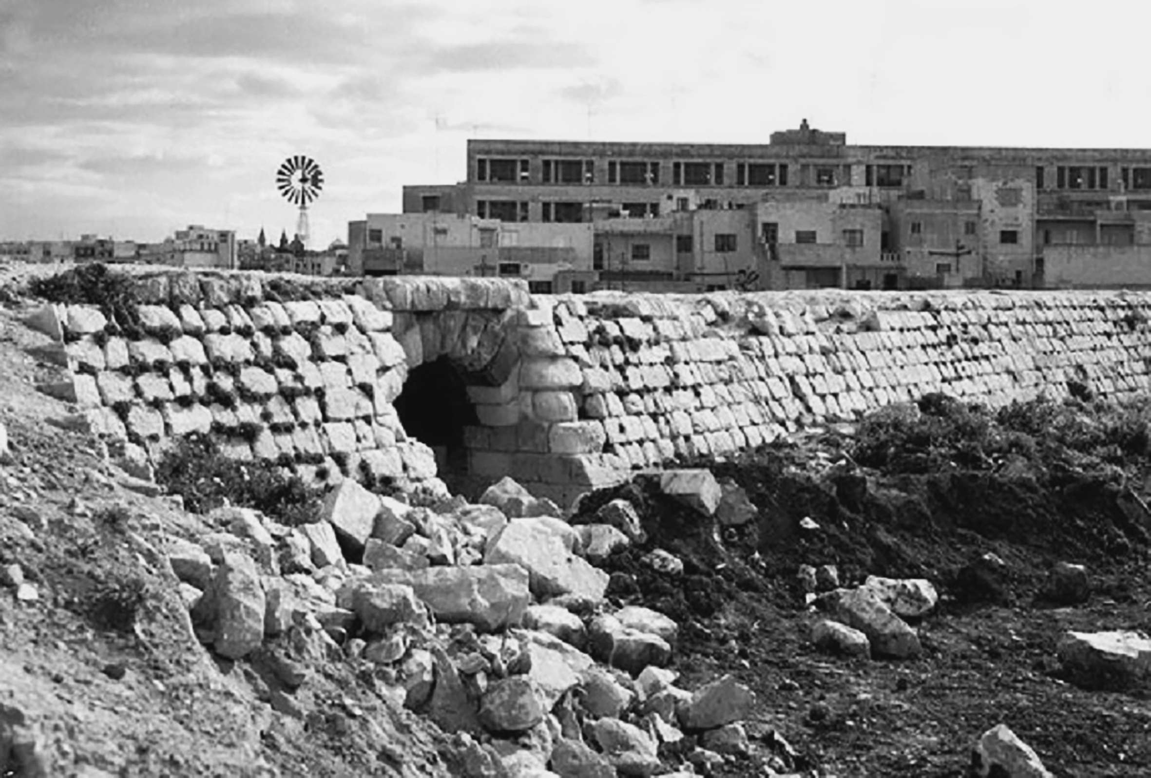
Although defence technology had progressed considerably during the 19th century the British Army continued to place great importance in the Renaissance and Baroque fortifications built by the Knights. They were cautious about the railway boring through in a way that would weaken them strategically. To ensure the new tunnel couldn’t be infiltrated by any would-be attacker, a room was dug immediately below St James’s Ditch. This vaulted chamber had three gun embrasures facing directly into the railway tunnel which had a higher vault built in this section intended to prevent smoke from obscuring the aim of the defenders. It was accessed down a set of steps from St Philip’s Gardens via a small secure lobby and was presumably maintained by the Army if not permanently manned. A final measure was planned, a deep pit designed to fill the width of the railway tunnel beneath track level with a “lift bridge” over it; this would prevent the enemy escaping the guns should they get that far. The structure survives today.
Going down again: Onward to Mtarfa
The arduous experience of digging the original tunnels didn’t put off the Government’s first manager Lorenzo Gatt in promoting the extension of the railway to Mtarfa. This would require a 770 yard long tunnel passing under the whole of the ancient citadel. Shorter than the Floriana tunnel it would prove to be more problematic and costly. The original conception was for another underground station close to the gates to Mdina, but this was later developed into a connection to the new barracks in Mtarfa as a more commercial proposition.
Digging began in 1896 and would drag on for almost four years. Rather than the rock anticipated, the tunnelling encountered unstable clay, difficult to dig and requiring a stone tunnel lining to shore-up the structure along much of its length. The tunnel spoil was carried out and dumped to form the Gheriexem valley embankment. Like the earlier tunnels, there were a number of shafts dug down through the ditch separating Rabat and Mdina for ventilation and to haul out waste from the digging operation deep below.
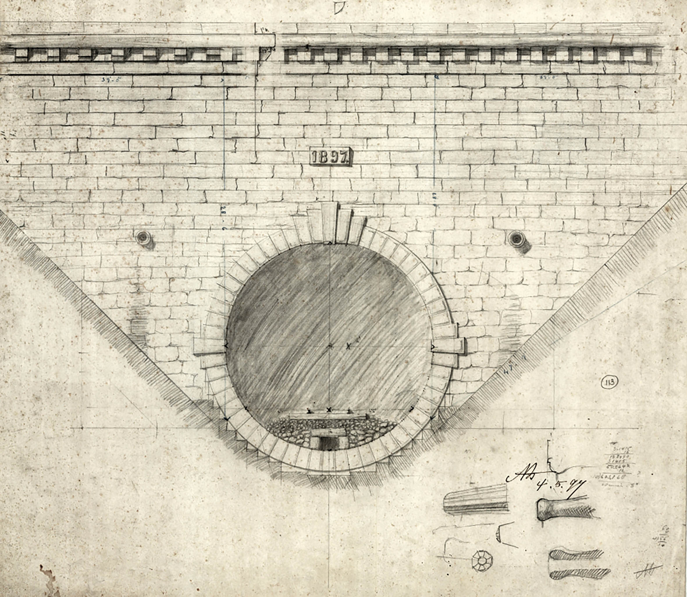
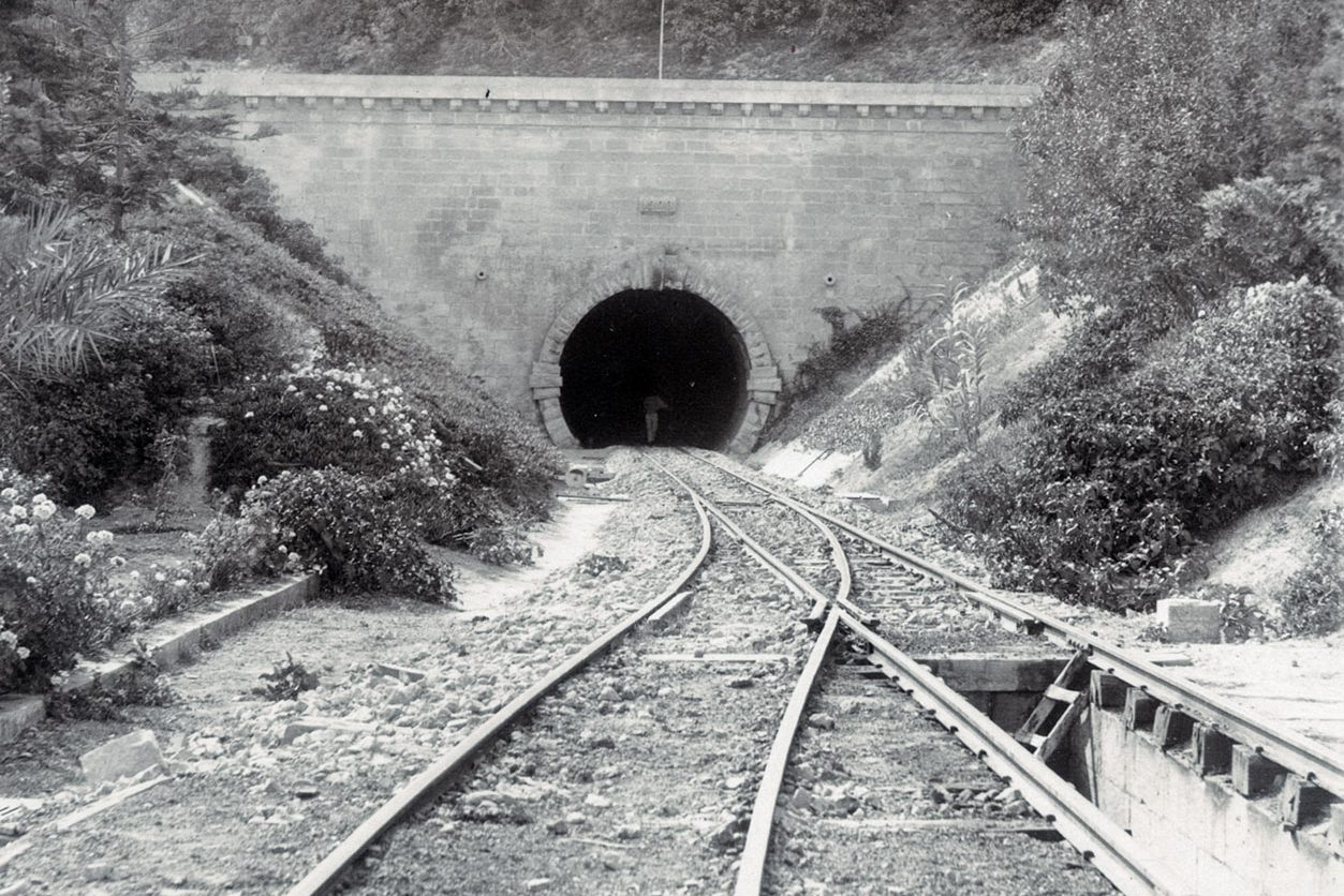
By the time the extension to Museum station opened in 1900 the project had gone over budget by £5,000, costing the Government £20,000 in total. Much of the overspend had disappeared into the tunnel works. This didn’t prevent each of the new portals being finished smartly with ashlar stonework, some simple architectural decoration, and, on the western end, a datestone carrying the year the tunnel opened. Not only was digging the tunnel challenging, it also had the steepest gradients on the railway. From a standing start at Notabile, this 1:40 ascent was punishing for the engines, despite the relatively short distance they covered before arriving at Museum.
Building Bridges
Gaining elevation
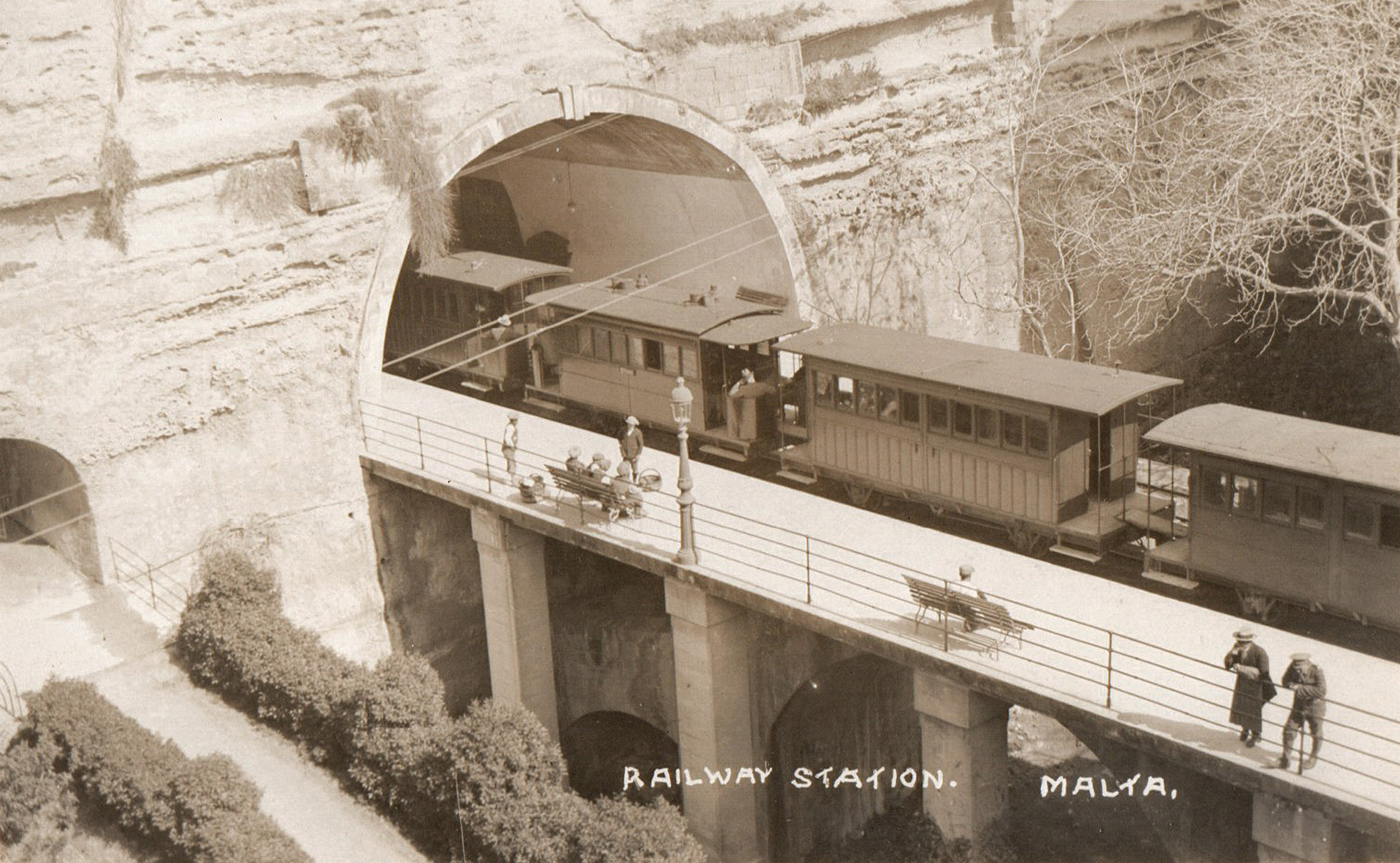
The moment trains left Valletta station they were immediately transported across the city’s main ditch by the first of many bridges along the line. There was a concentration of these structures at the eastern end of the railway where the walls and ditches of the fortifications complicated engineering, but they were by no means unique; many bridges were simple underpasses beneath the line for farmer’s use. But, there were more memorable structures at Attard, where the main road needed to be crossed at height, San Salvatore, where the road passed over the track, and, most dramatically at Museum where the Gheriexem valley needed to be crossed.
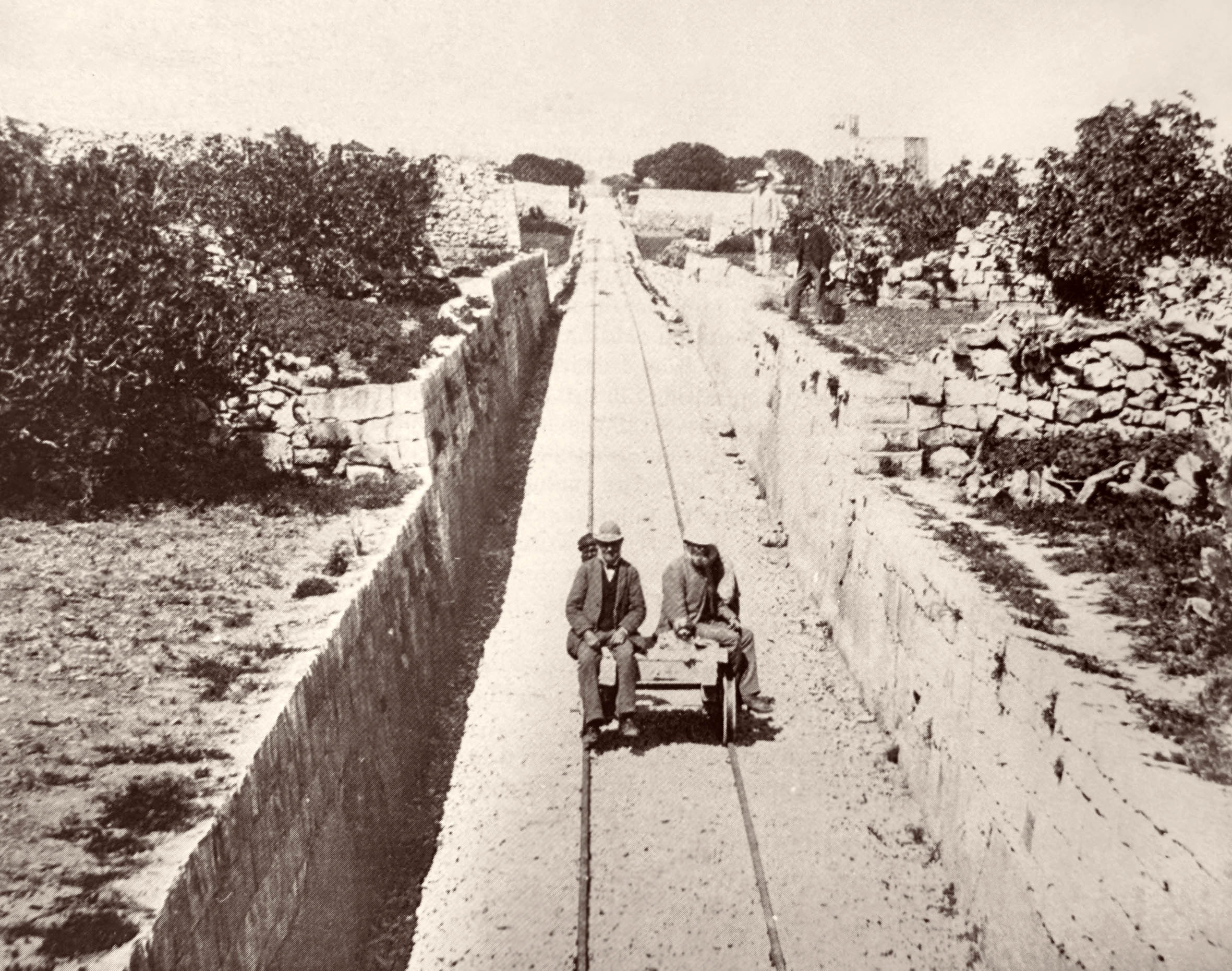
Also worth exploring in this section are the cuttings and embankments that ensured the line continued on a level gradient. In an effort to reduce the impact on Malta’s valuable farmland embankments were built with steeply angled stone walls rather than the tradditional banked earth, “the train consequently presents the curious appearance of running along the top of a wall”. Only the embankment at Museum station differed, with steep earthworks that ate up much land. Cuttings were generally dug directly down into the bedrock.
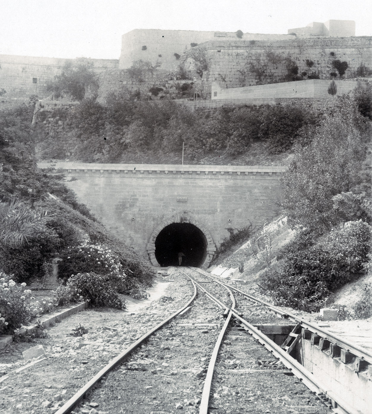
The first three bridges out of the Capital began as simple timber structures. These immediately abutted tunnel mouths as the line alternated quickly between underground sections and being projected precipitously over several defensive ditches dug by the Knights to protect Valletta’s landward approach. Whilst timber may have been cheaper than the equivalent in stone, the materials were prescribed by the British Military.
Keen not to see the new railway weaken the city’s defences, the railway had to ensure they could be easily and quickly removed should the city be threatened. An additional obligation was to include further “drop ditches”, large pits, to coincide with each penetration of the fortifications and crossing of the historic ditches. These were to deprive any ladder-equipped enemy from an easy time in accessing the tunnel openings from below.
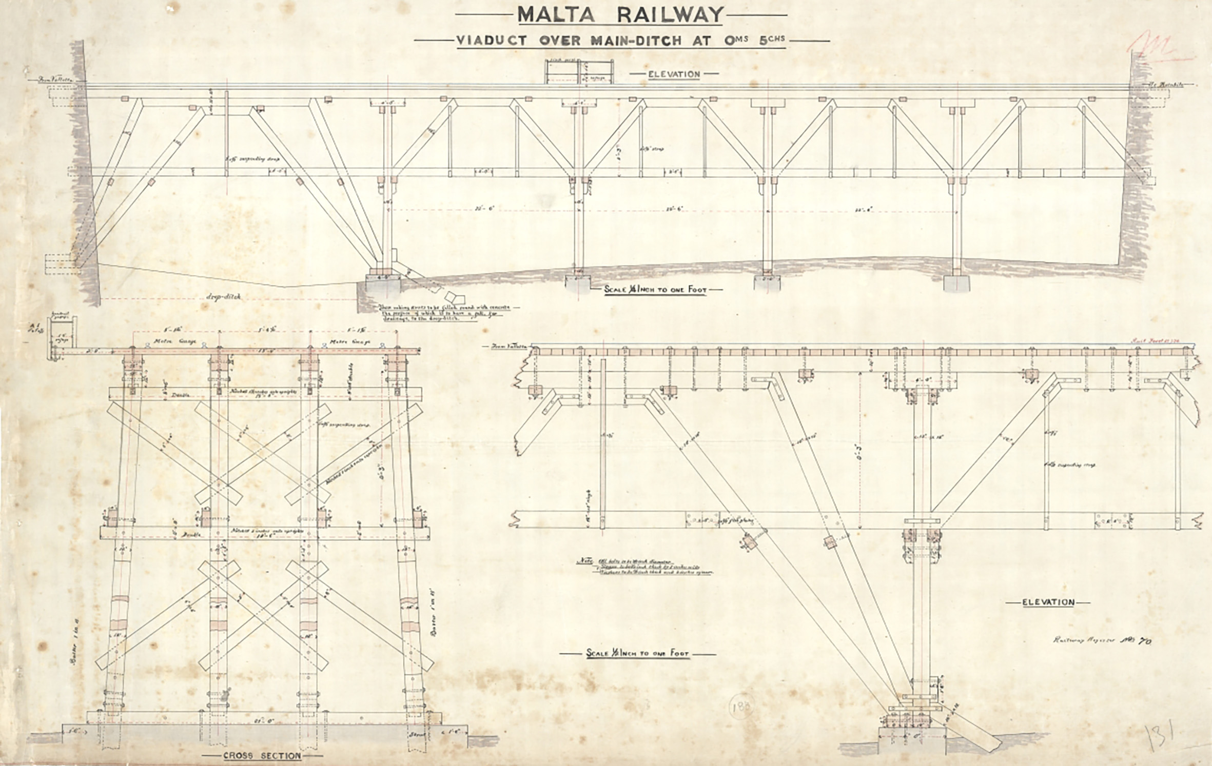
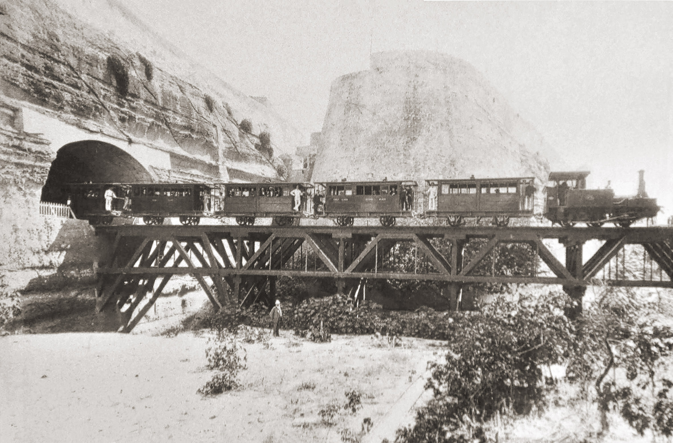
Early photos of the bridge across the main ditch make it look rickety and dangerously exposed. This would ultimately lead to its accelerated deterioration in the Maltese climate; an unavoidable inconvenience in the face of pressure from the military authorities. It was of five spans, four of which were supported on timber piers. The first span needed to vault over the drop ditch immediately outside the station portal and was necessarily wider, propped directly off the city wall and from the bottom of the ditch. From the start this bridge was designed for two tracks that narrowed to one before entering Floriana tunnel.
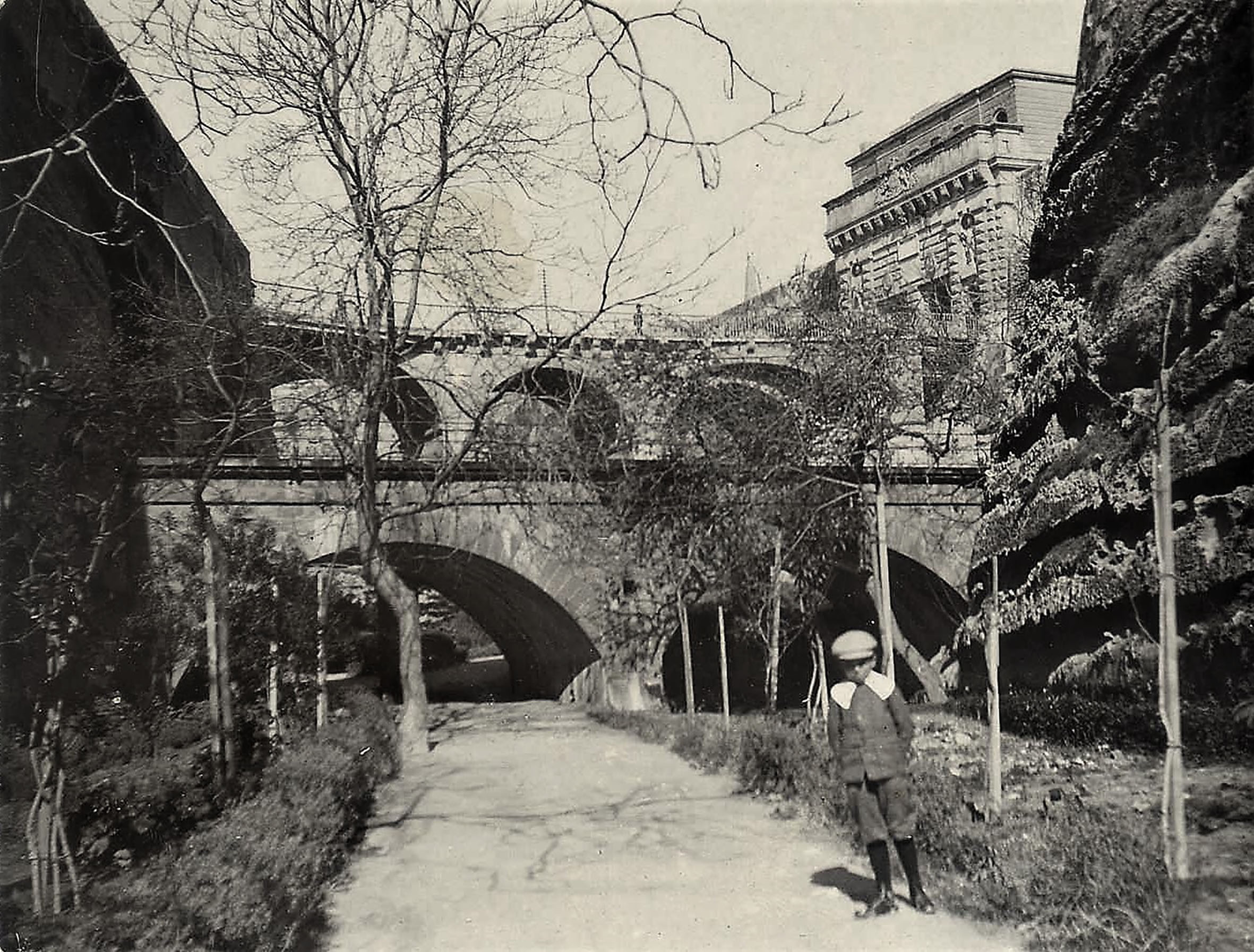
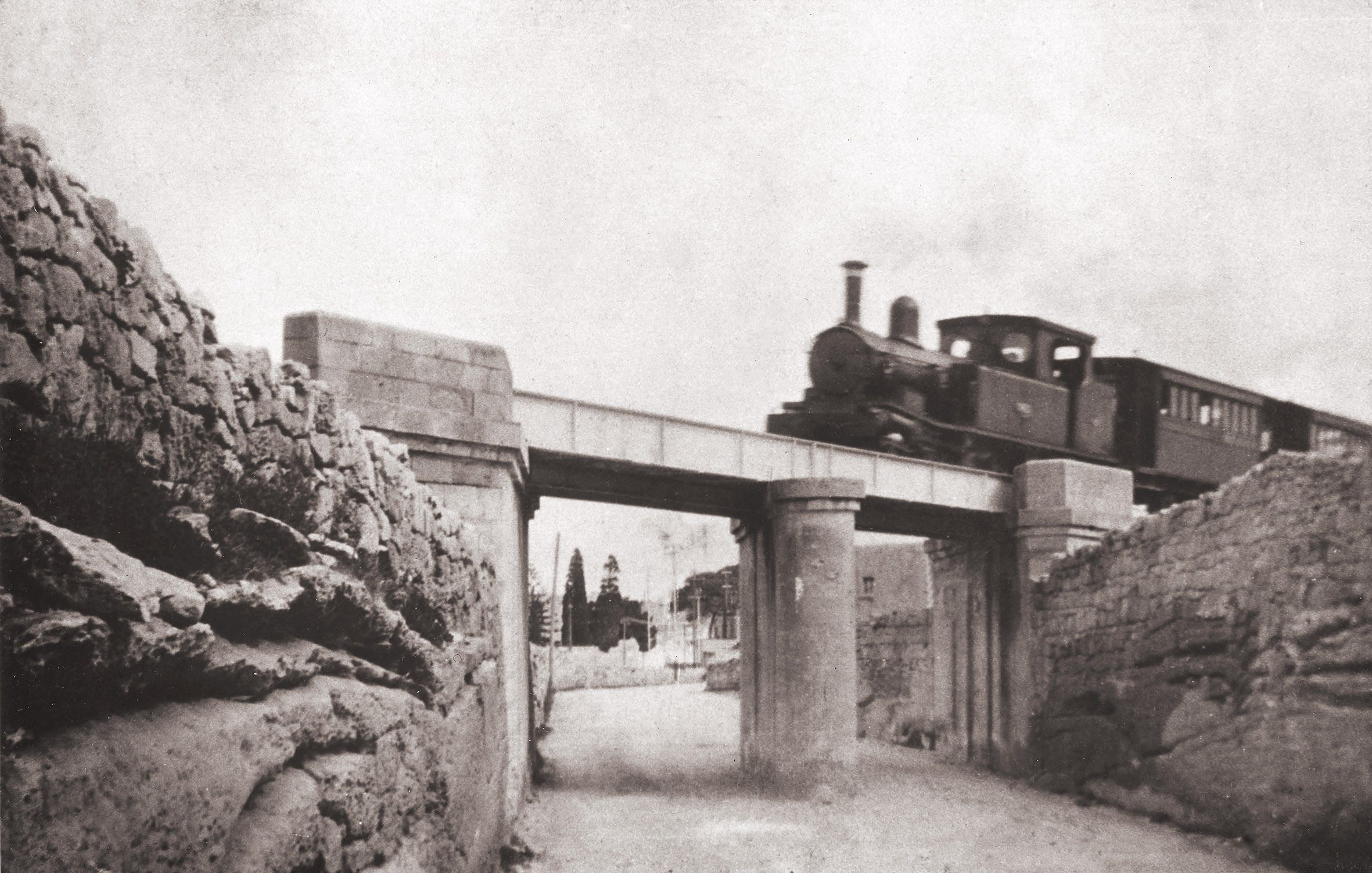
Astonishingly, having lasted just eight years, Valletta’s bridge was condemned in 1891 by inspectors. This made it a key priority for Government to fix before they could re-start train services after the old company had collapsed in debt. In such a short space of time it’s strange that the Army had lost interest in interfering in designs and allowed a largely stone viaduct. Replacing the old bridge a new arched stone viaduct was built with three shallow arches.
This structure remained separated from the station mouth by a gap of 14 feet across which timber baulks supported the tracks; this way the Army could maintain their firebreak in the city defences, at least until 1902 when a new stone arch replaced them. The first of the bridge piers had to be built directly out of the drop ditch, the lateral forces imposed by the arches being buttressed by a series of small stone arches connecting with the base of the city wall.
The bridge was widened again in about 1898 with a platform extension built across old rails perched on stone piers, but this perfunctory and unattractive addition was recently demolished, returning it closer to its original appearance. As part of the new Parliament and city gate project the bridge was restored, a post-war ramped road removed and its decorative iron railings repaired.
Penetrating the city lines
The next two bridges on the line spanned Notre Dame ditch and the fosse bray ditch at the very perimeter of the defensive array. Like the Valletta viaduct, these were initially wooden and incorporated drop ditches. In order to protect the entrance to the Floriana tunnel, Notre Dame bridge was entirely in its own ditch giving rise to the misapprehension that this had been a drawbridge. It was a very simple structure of trestles and beams designed to carry just a single track.
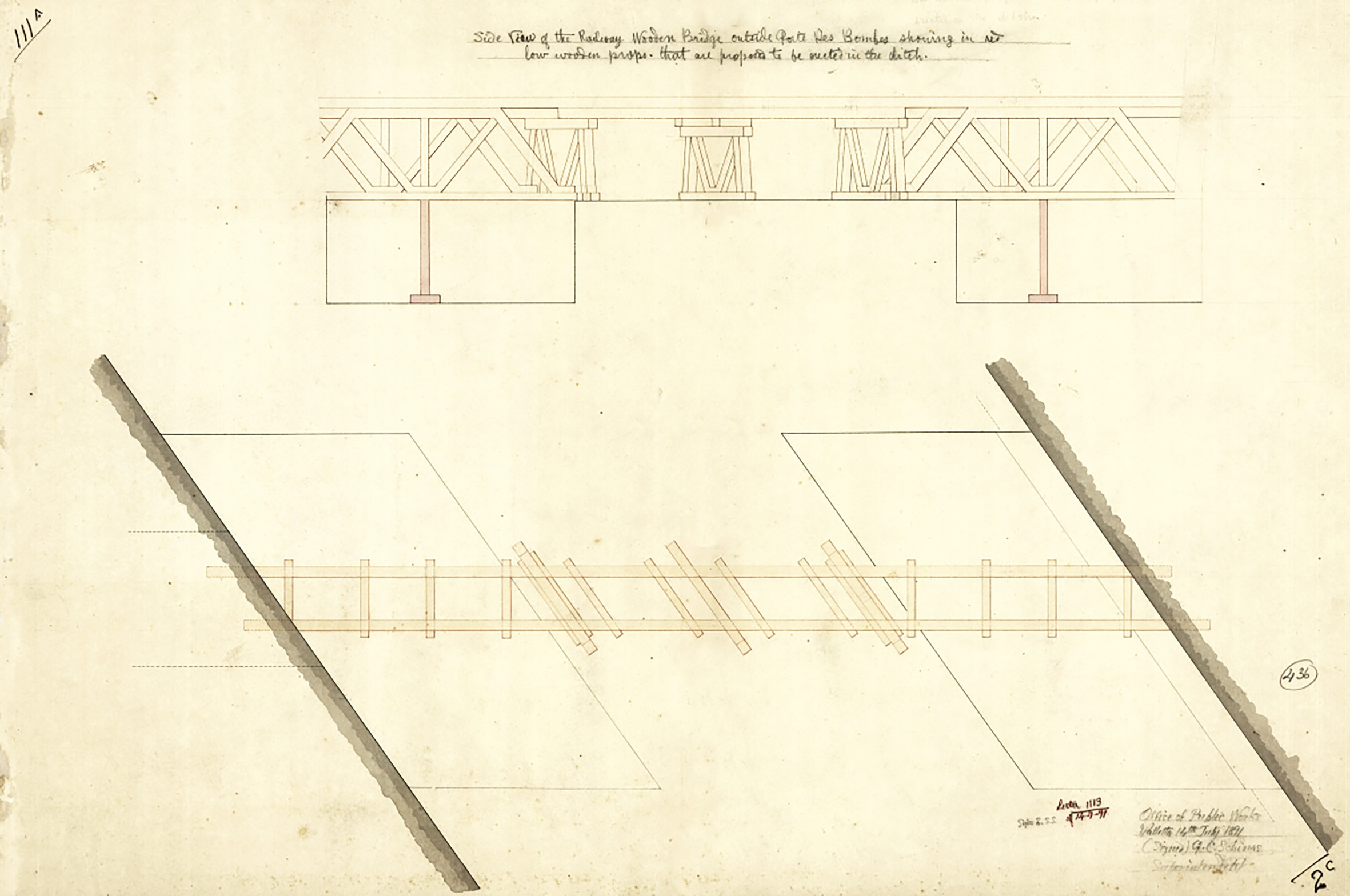
The structure of the final crossing in this sequence, close to Porte des Bombes, was complicated by the angle at which the line left the fortifications and the need to incorporate two drop ditches at either end. This was bridged by short trusses with the shorter central section using skewed trestles. Like Valletta’s viaduct, the timber construction resulted the structures declining quickly. A quick fix was engineered with additional posts propping the bridges up across the drop ditches, but eventually complete replacement was unavoidable.
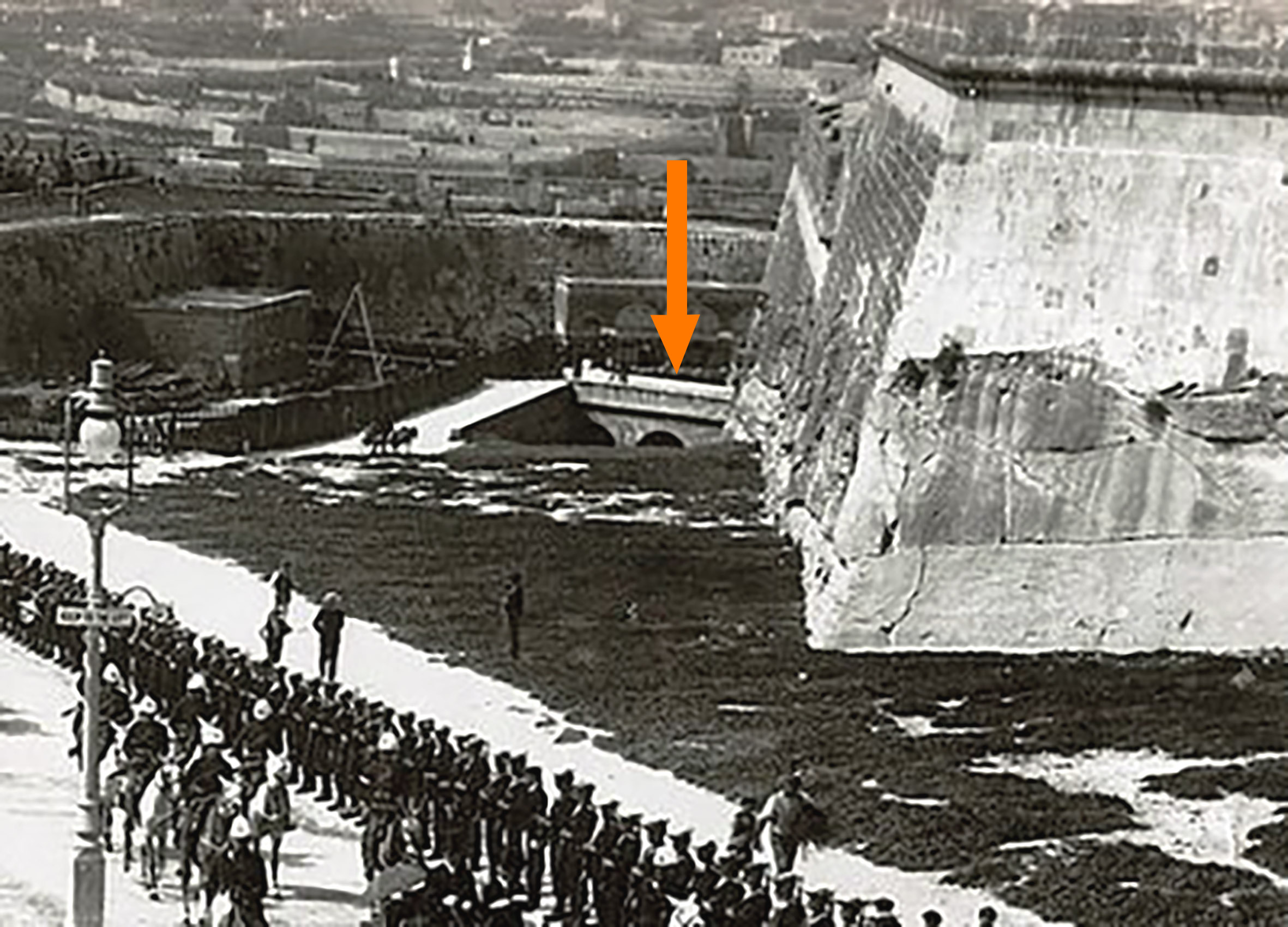
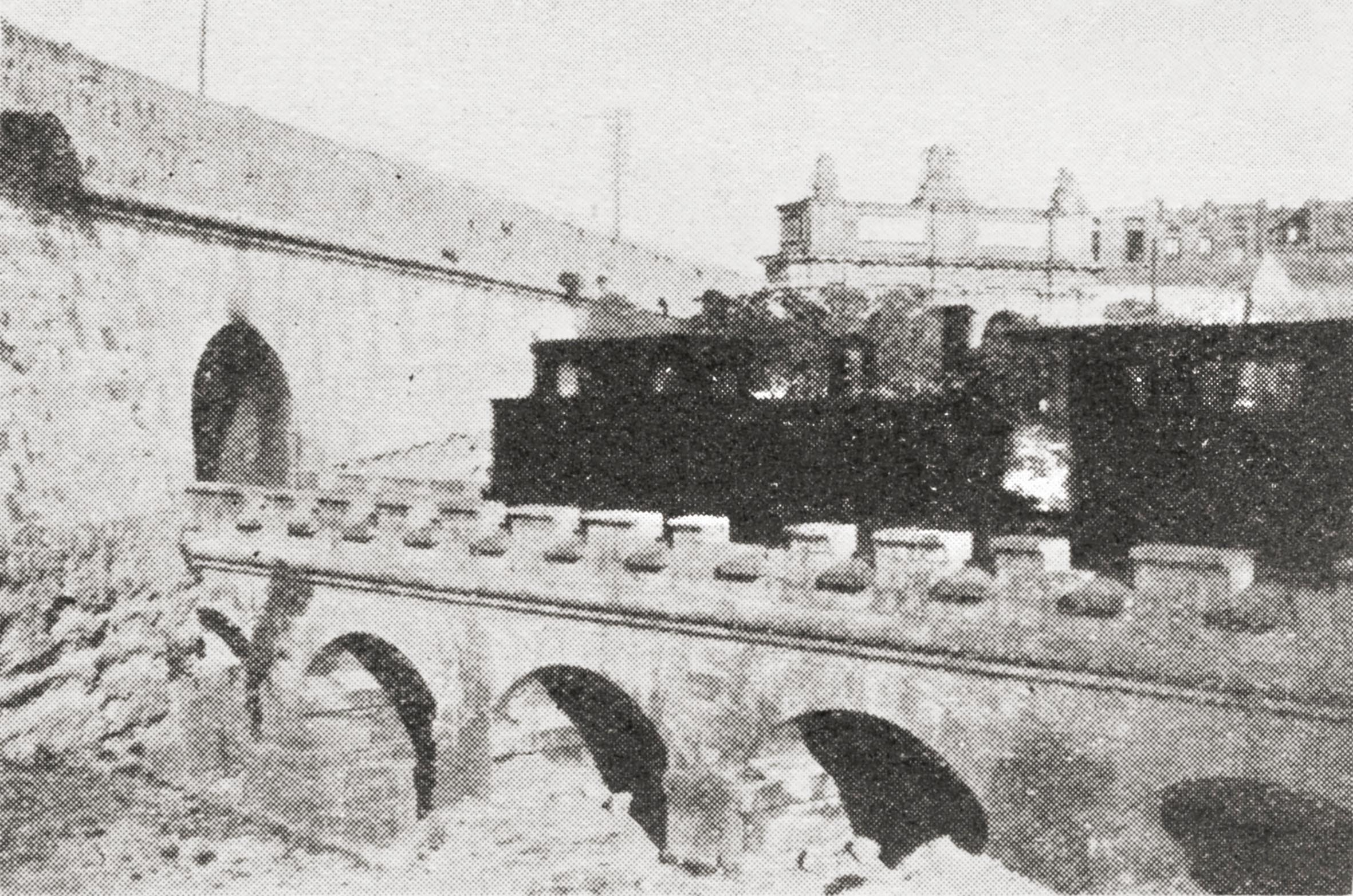
The surviving bridge, still visible today from the busy dual carriageway that ploughs through the old walls at Porte des Bombes, was erected in 1894. Despite the suggestive addition of castellated parapets, no effort was made to build anything defensible; these crenulations were entirely decorative. Five stone arches span the ditch, though the drop ditches have subsequently been infilled. Enough evidence survives below the bridge to trace where these and the original timber bridge piers stood.
Beyond the walls
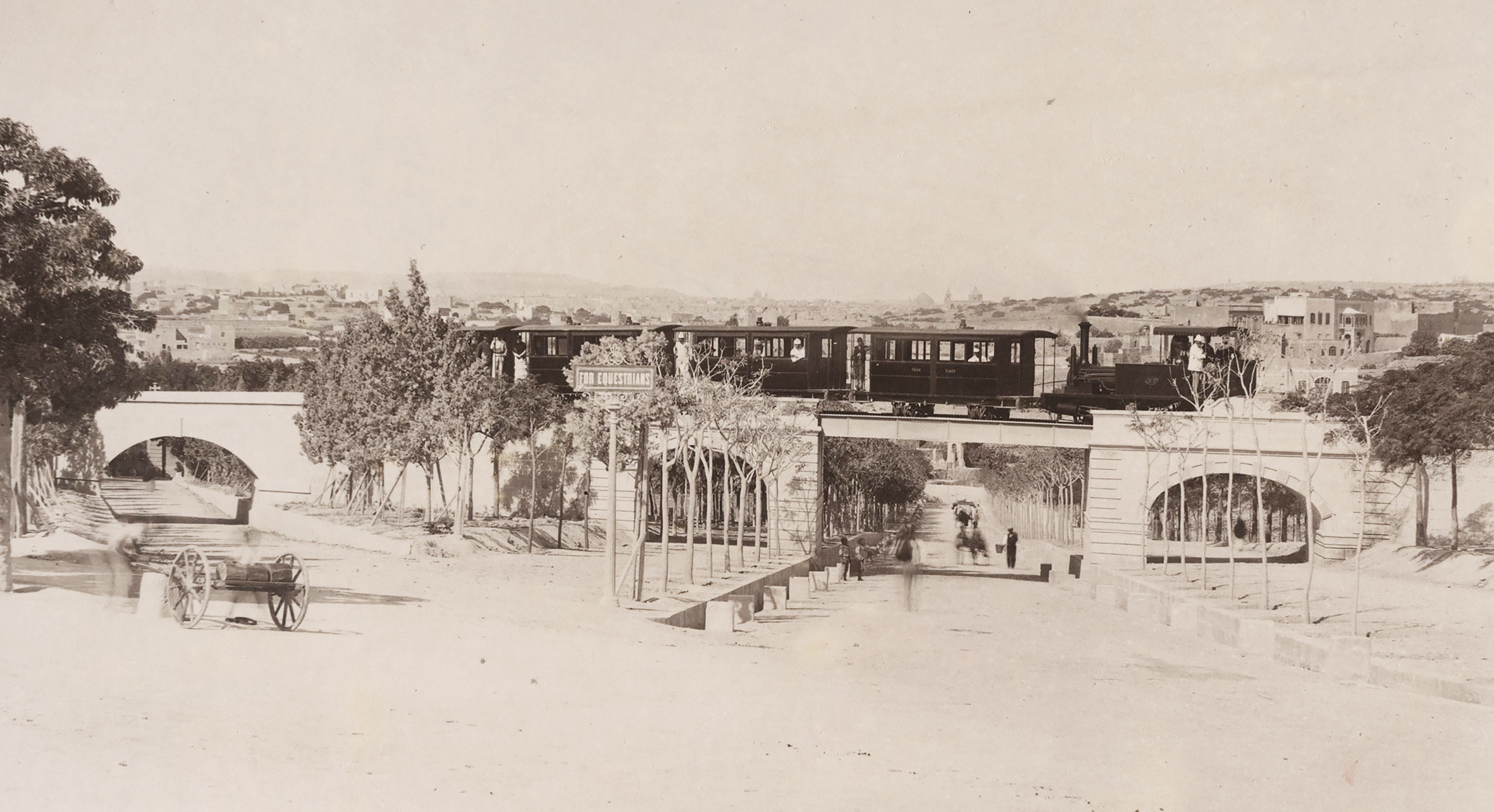
As soon as the line was free of the defensive lines it was immediately called on to clear the Princes Melita Avenue at a raised level. Freed from military demands a more permanent and attractive structure was designed here This may have been one of the “three skew bridges” designed for the railway by Maltese architect Andrea Vassallo. Developing his career from mason to engineer and then architect, by 1883 Vassallo was already an accomplished designer, having erected villas and houses for high profile clients.
During the construction of the railway he may have been contracted on projects outside of the scope of the London Engineers, and is unlikely to have found his skills best used on the timber bridges that were more basically engineered. It’s likely he worked on further railway works after 1891 when the Office of Public Works became responsible for providing engineering and architectural support for the Government-owned railway.
Two handsome rusticated stone arches were thrown across the bridleways that ran parallel to the main road; this had to be lowered slightly to increase headroom and was spanned by a slender steel plate girder bridge section that looked barely up to the task of supporting trains. In the event this proved to be the literal case, additional corbelling having to be built to prevent the steelwork deforming after heavier engines were introduced from 1892. The limited clearance below the bridge was already a nuisance to vehicles before the introduction of busses, and the structure was quickly removed on the line’s closure in 1931.
Beyond Ta’ Braxia bridge, effectively a miniature replica of the Princess Melita Avenue bridge and practically adjoined, the line passed through an agricultural landscape. Stone revetted embankments were required on the approach to Hamrun, where an underpass was encountered at the station limits. The long curve of the line to Msida required a cutting before opening out into a tall handsome embankment brought the line into the station.
There were more underpasses in this section to satisfy farmers whose land was divided by the construction of the railway.
Whilst it was never constructed, there was a plan to dig an underpass for the Fleur de Lis Road at the entrance to Birkirkara station. This would have been a wide skewed structure with a stone arch across the street, but the plan was abandoned for financial reasons and the level crossing remained a dangerous feature. More relatively low stone embankments elevated the line above the fields through Balzan and San Antonio before more substantial structures were needed to deliver trains into Attard station.
To Attard and the high lands
The tallest embankment on the line started just beyond San Antonio, close to where the modern Corinthia Palace Hotel stands. The line here formed a gentle S-bend that gave added emphasis to the elegant storey-high stone structure, with gently battered walls finished to a high standard. This veritable bulwark along which the train travelled was broken only by several farmer’s underpasses. Surprisingly, this monumentally tall section was never demolished for conversion to a road and survives today split by the Birkirkara Road; In the railway’s day this was spanned by another bridge.
The Attard viaduct was a simple affair. The stone embankments terminated in substantial skewed abutments, more brutal in character to those at Princess Melita Avenue and somewhat taller. The design is possibly another of architect Andrea Vassallo’s rather than a product of Wells Owen & Ewes office. Here, the road also had to be changed to create headroom and needed cutting directly down into the rock to allow the line a level passage above it.
Slender steel plate girders were used again to span across the road, so slender as to need an intermediate stone pier built directly into the middle of the roadway. It would have been entirely possible to engineer a solution to take the line across the road without this additional highway hinderance, but, one assumes, the Company had done their calculations and proved that the mason’s bill would be less than that of a steelworks.
Like all the original bridges on the line, there was no protection provided along the bridge edges, nor to any of the perilously steep embankments. Indeed, Attard viaduct was the site of an unfortunate fatality when one of the station staff fell from the abutment into the road. Had a train broken down on these tall structures, or an accident occurred, it’s difficult to see how passengers could have safely disembarked.
More sheer than the embankments were the walls of the cutting, hewn directly through shallow soils into the island’s bedrock. A stretch immediately beyond Attard was the deepest of these before Notabile was reached. Sets of steps were cut into the soft rock to allow the line to be crossed to access fields and, where the depth of the cutting allowed, an arched stone overbridge was a more generous option.
Between Attard and Notabile the gradient increased and the line was characterised by many more cuttings and embankments on its journey uphill, mostly of a minor nature. At San Salvatore, a low bridge crossed the Wied ta’ Rmiedi watercourse at the eastern end of the station, whilst the western end was contained by a road bridge carrying the Mdina road over the line.
When the railway opened in 1883, this had been a level crossing, but road and track met at a sharp angle that damaged cartwheels which, in-turn, damaged the permanent way. Things came to a head in 1890 when Chief Justice Sir Joseph Carbone’s carriage had its wheels ripped off by the crossing. It wasn’t until three years later that, in Government hands, the railway acted, constructing an expensive new skew bridge in stone, diverting the road up and on a curvy course but out of the way of the trains at least.
Extending to Mtarfa
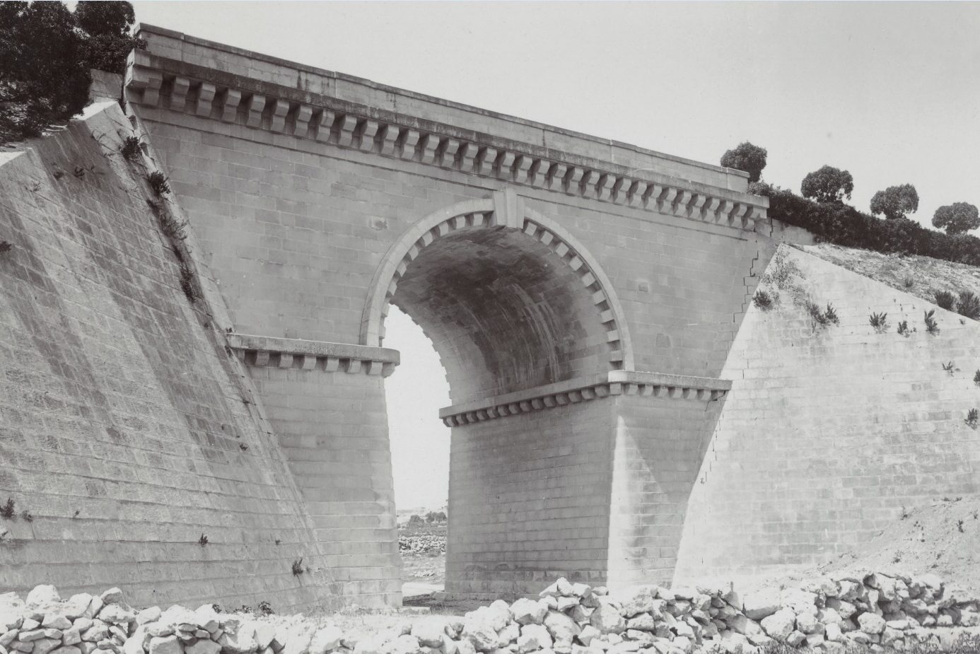
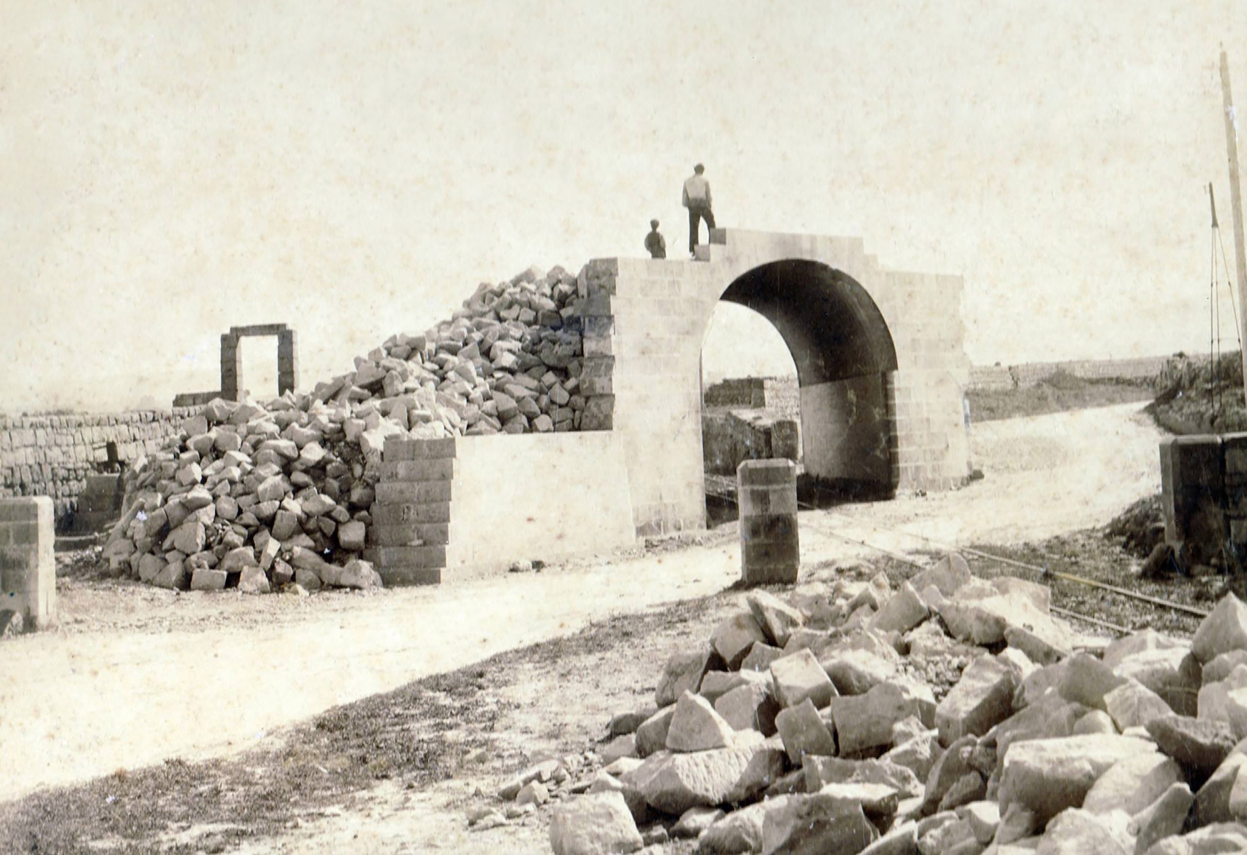
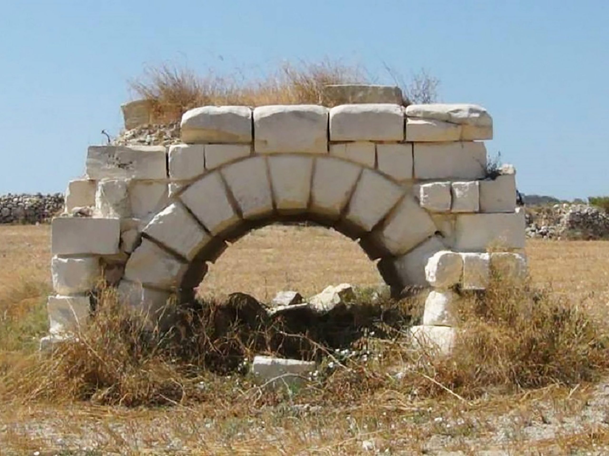
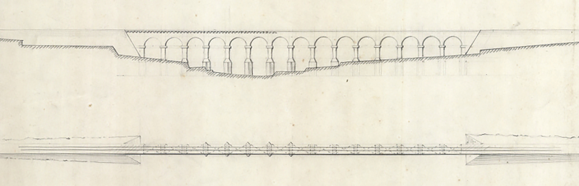
By far the most impressive bridge on the Malta Railway, its most monumental structure, was the Gheriexem bridge. When plans were approved for the extension of the railway to Mtarfa in 1895 it required the crossing of the valley on the other side of Mdina at a high level. Initial designs proposed a fifteen-arched stone viaduct; this was probably rejected as being impractical. Instead, a monolithic embankment was projected that at its midpoint would incorporate a single-arched bridge across the stream in the valley bottom. The scale of the endeavour required more substantial works than those encountered with other embankments on the line, and a far greater land-take. Conventional earth banks were thrown up, partially from material dug from the new tunnel but the quantities needed must have required much more.
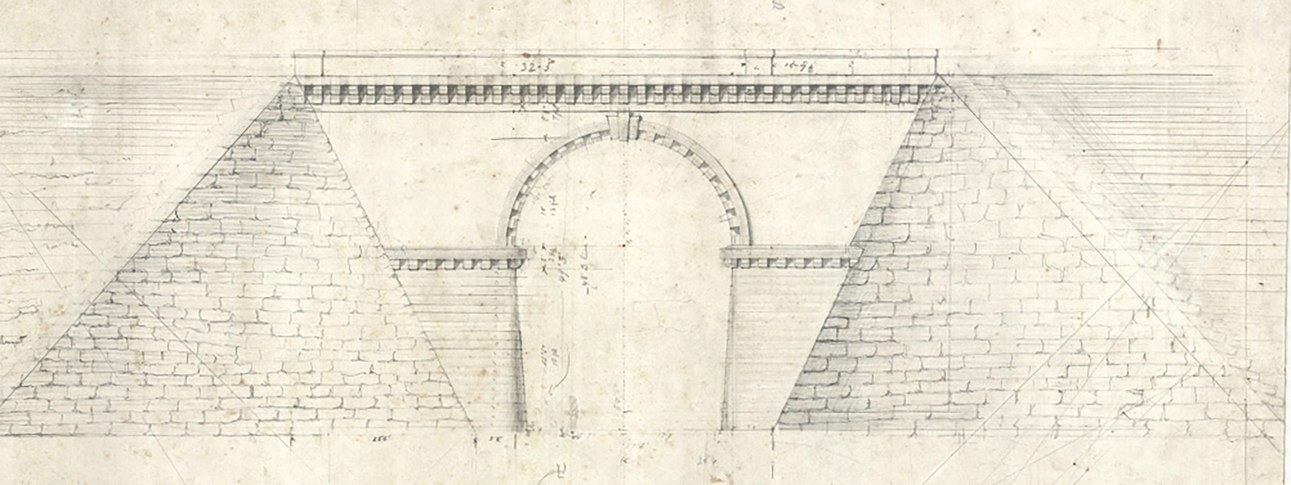
Rather than being another utilitarian structure, the bridge was a bold architectural statement with chunky details, giant corbels and cornices of suitably expressive character for its scale and stature. Even at a distance, the qualities of the design would be easily appreciated. It would usually be down to the Office of Public Works to supply drawings for major Government projects, but surviving drawings aren’t signed by their superintendent and are instead signed NB, suggesting Buhagiar was responsible. With architectural and civil engineering training, he would have been capable of such work. The monumental design and decorative features are boldly executed with a clear eye to beauty and posterity.
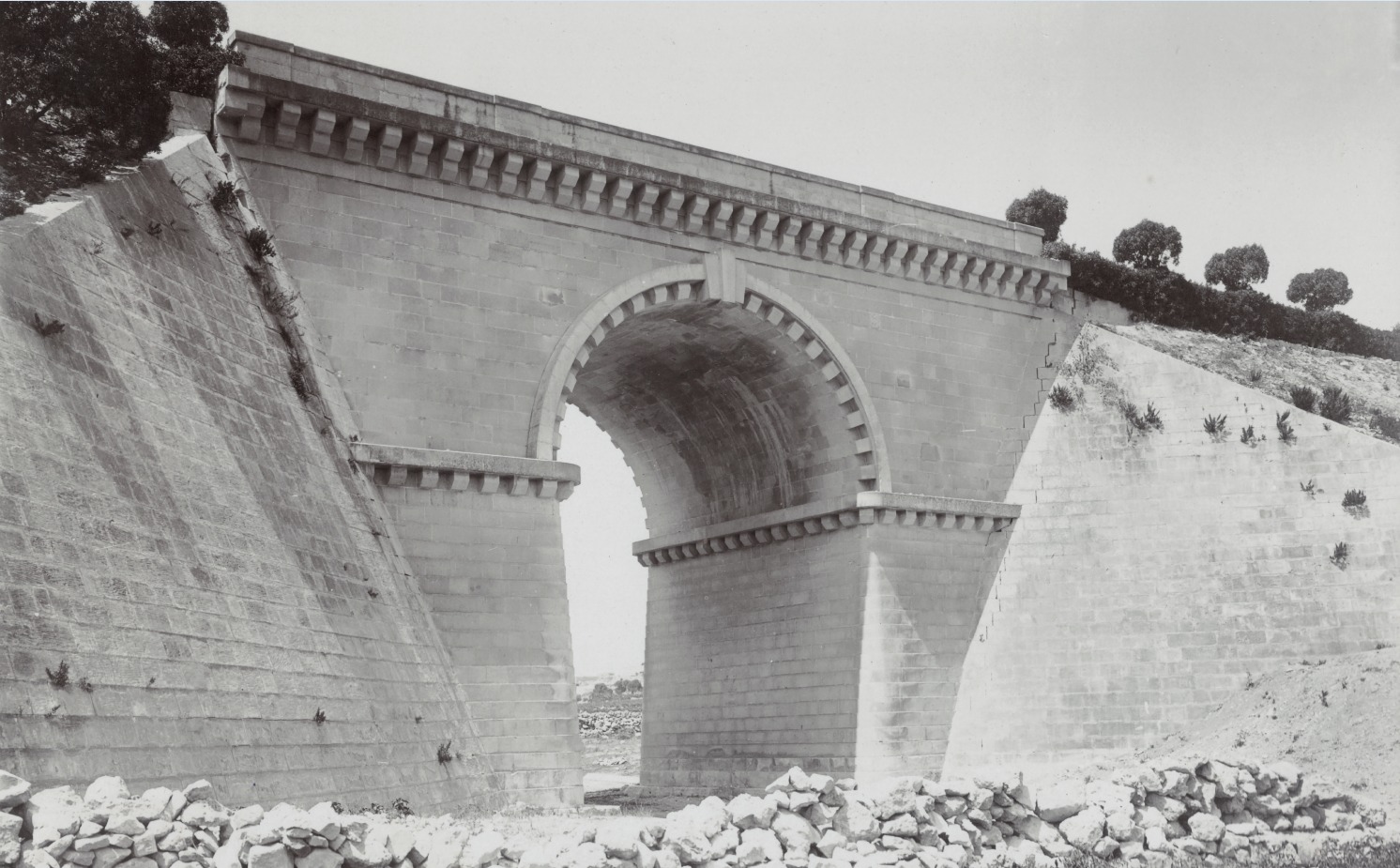
With such a large embankment it’s unsurprising that it suffered settlement in the first few years after the extension opened in 1900. Some of the bridge stonework cracked in this slump, particularly where the flanking retaining walls connected with the bridge structure. These cracks stabilised but can still be seen on the surviving bridge today.
